Temperature Mapping for Pharmaceutical Industry

Temperature mapping is important for verifying the efficacy of temperature controlled storage systems such as cool rooms, fridges and warehouses. It is vital for businesses that work with temperature sensitive products such as pharmaceuticals or warehouses.

The process of mapping outlines the differences and changes in temperature that occur within a single temperature controlled system. This is due to influences like opening doors, proximity to cooling fans, personnel movement, and the quantity of products being stored at any given time. Temperature mapping locates the points of greatest temperature fluctuation and difference then analyses the causes of these. Conditions are created to verify that a system maintains the correct temperature in all situations when influenced by external factors such as weather and internal factors such as airflow restrictions and the operation of the Heating, Ventilation and Air Conditioning systems. The effects in difference of temperature are calculated to ensure the systems meet industry standards.

The temperature of different spaces within cooling rooms, industrial fridges and other controlled temperature environments can vary by up to 10°C. Generally, the central space within a chamber maintains constant temperature, however the corners and areas surrounding the fans will fluctuate. External seasonal weather must also be taken into account especially for warehouses.

Temperature mapping is important for businesses and organisations dealing with temperature sensitive products, like biochemical products such as medications and vaccines. Verifying that the refrigeration systems maintain an acceptable temperature level for each specific product at all times is what temperature mapping is all about, and this is supported using ongoing monitoring systems.

Once mapping has established where temperature variation points lie within the control system then monitoring can be installed. It is important to re check any back up systems to be sure that the chambers will work in other circumstances.

Different mapping equipment gives different results. It is important to ensure that the equipment being used has sufficient accuracy ratings to give reliable data. For example, better equipment will provide readings that are accurate within plus or minus 0.3°C, whereas budget equipment may only have accuracy ratings of within 2.0°C. For products that must be stored within a limited temperature range, this budget equipment cannot provide sufficiently specific temperature data.

Warehouses must have information regarding the building’s external conditions, as it is vital for effective mapping and monitoring. Warehouses are generally mapped for a full year to ensure all external conditions are accounted for in the data. This also helps to determine placement of monitoring systems due to influence of external conditions.

Temperature-controlled rooms such as fridges or cold rooms can be mapped once as their external environment is controlled. However, it is advisable to make sure that other external forces that could change their temperatures significantly do not heavily influence the HVAC systems of these buildings or environments. The mapping in warehouses should take into account the fluctuation in the warehouse temperatures and conduct the tests during its most extreme levels.

Load testing is important aspect of the temperature mapping process. It investigates how expected product levels interact with individual temperature controlled chambers. This testing takes into account whether the product will arrive in the required condition or if cooling is necessary. Testing should verify whether the chamber could cope with the maximum specified load arriving all at once to then be cooled. If it can operate properly in this situation, as well as operating effectively at full capacity, the chamber can be considered sufficiently load tested. It is also advisable to test the system’s performance by simulating failures, to ascertain whether the system could be used even while experiencing some equipment failures.

Once the mapping process has been completed, sensors should be installed to allow for continued surveillance of the areas that have been identified as being most influenced by temperature change. The stable areas should be monitored to help with any troubleshooting.

Monitoring systems should be planned and documented according to the scientific rationales shown by the temperature mapping procedure. This development strategy should then be reviewed and approved by the system owners as well as by an independent quality unit before being installed. Sensors should be placed around the products, around major potential temperature influences such as doors and cooling fans, and at different heights, especially in larger chambers.

Sensor equipment can be split into zones according to the area affected by similar influences. For example, in a square or rectangular chamber, the zones in corners away from doors will behave much the same as each other, as will the zones adjacent to doors or fans. If the monitoring devices are zoned, data can be compared to provide overall information on how the system usually functions.

To summarize, temperature mapping provides information on warmer and colder areas within temperature-controlled environments. They supply details on the overall operation of the systems. After temperature mapping a system, monitoring equipment can be installed to provide real-time feedback on system operations and its stability for product protection.

Clean steam systems in the Pharmaceutical Industry

What is clean steam?

Clean steam is used in the pharmaceutical and healthcare industries in processes where the steam or its condensate can come into contact with a pharmaceutical or medical product and cause contamination. In such cases, steam from a conventional boiler(often called utility or plant steam)is unsuitable because it may contain boiler additives, rust or other undesirable materials.+

The use of clean steam is determined by the rules of Good Manufacturing Practice (GMP). These are general rules applicable to pharmaceutical manufacture,detailed in the Code of Federal Regulations(CFR Title 21,Part 211). They do not provide any specific recommendations regarding steam, but do present the general requirements offacilities, systems, equipment and operation needed to prevent contamination of pharmaceutical products during their manufacture.

Uses of clean steam:

The main use of clean steaming pharmaceutical manufacturing is for the sterilization of products or, more usually, equipment. Steam sterilization is encountered in the following processes:

  • Manufacture of injectable or parenteral solutions, which are always sterile.
  • Bio-pharmaceutical manufacturing, where a sterile environment must be created to grow the biological production organism(bacterium, yeast or animal cell).
  • Manufacture of sterile solutions,such as ophthalmic products.

Typically in these processes, clean steam is injected into equipmentor piping to create a sterile environment, or into autoclaves where loose equipment, components (such as vials and ampoules)or products are sterilized.

Clean steam may be used for some other functions where conventional utility steam might cause contamination, such as:

  • Humidification in some clean rooms.
  • Injection into high purity water for heating prior to Clean-in-Place (CIP) operations.

Fundamentals of clean steam system design:

Avoidance of corrosion

Unlike utility steam, clean steam has no corrosion inhibitors. Also, low conductivity water or condensate is hungry for ions, causing it to be corrosive to many materials commonly used in utility steam systems. Carbon steel,gunmetal and bronze, all commonly found in utility steam components, would all be rapidly corroded. Metal components for clean steam systems are therefore usually AISI 316 L stainless steel, or sometimes titanium. Non-metallic materials used include EPDM and PTFE.

Then eed to avoid corrosion is not only necessary for safeguarding the integrity of equipment. Corrosion products entering the clean steam could potentially cause contamination of the pharmaceutical product, either as chemical or particulate contamination.

Even where 316l stainless steel is used, a particular form of corrosion, called “rouging”, is often encountered in clean steam systems. The passive layer on the steel surface is disrupted and a red/brown/black film develops over time. Often this film is stable and does not pose a threat to the pharmaceutical product. Sometimes a powdery film develops and this can detach from the steel surface and cause discoloration of equipment which the steam contacts.
If this occurs, and the manufacturer feels that there is a risk of contamination or discoloration of the product, then the clean steam generator or even the full distribution system may be cleaned (“derouging”).

A variety of methods are used, but they all involve a chemical treatment to remove the surface layer of steel – this is essentially an etching process. After de-rouging, a passivation process must be used to restore the passive layer on the steel surface, since it is the passive layer that is responsible for corrosion resistance.

Preventing entry of contaminants into the system

Clean steam must be free of contaminants at the point of use. Chemical and microbial contaminants can enter steam systems in a variety of ways, and in the design of clean steam systems this must be avoided. Pathways for contamination include leakage, air being pulled into the system and “grow through” from a contaminated external environment.

Preventing microbial growth in the system

Steam at typical operating pressures will kill bacteria and their spores, so the parts of a clean system that are continuously exposed to steam will be sterile. However, if condensate is allowed to collect in the system, and it cools, then stagnant water can provide a suitable environment for bacterial growth. Though these bacteria may be killed when the condensate is discharged into equipment, followed by steam, their breakdown products, including endo toxins, may still be present. Endo toxins are not destroyed by typical clean steam system temperatures.

Looking for a clean steam system design consultant? Look no more, contact Panorama now!

Fire Protection and Safety

Irrespective of its occupancy status, a fire can happen at any time and any place.
Fire has the potential to cause harm to its occupants and severe damage to property. Fire doesn’t only interrupt the whole process of manufacturing and production but also can cause major damage to the building and plant. Much work will be required in order to restore the entire production process.

Successful prevention of fire depends solely on the management who must survey the operation of the business and determine where the loss potential lies.

Inadequately maintained machines can be fire prone. The overheating of bearing, due to insufficient lubrication or the presence of dust, and heat caused by friction are common causes of fire. Frequent inspection and regular maintenance will reduce risk and make the general tidiness of premises easier to achieve.

Major fires start in storage area and warehouses than production areas. Poorly stored goods, even though they are not flammable, may help to spread fire and hinder fire fighters gaining access to the seat of the fire or reduce the effectiveness of sprinkler systems. Goods tidily stored with gangways may help to inhibit the spread of fire.

Fire Safety Audit

Fire has been rated as the 5th largest risk in the Indian Industry. Electrical defaults are the major causes of fire in India. Fire Safety Audit is found to be an effective tool for assessing fire Safety standards of an organization. In other words, it is aimed to assess the building for compliance with the National Building Code of India, relevant Indian Standards and the legislations enacted by State Governments and Local Bodies, on fire prevention, fire protection and life safety measures.

Though fire safety audit is found to be an effective tool for assessing fire safety standards of an occupancy, there is no clear cut provisions in any of the safety legislations in India, regarding the scope, objective, methodology and periodicity of a fire safety audit. Therefore, Fire Safety Audit should be made mandatory for all over India and the work should be entrusted to independent agencies, which have expertise in it. It is reasonable to have a fire safety audit in every year.

Clean agent suppression systems

Clean agent fire suppression systems make the use of inert gases and chemicals in extinguishing a fire.They are also known as gaseous fire suppression. In these systems, fire is suppressed manually or automatically by reducing heat rather than reducing oxygen, reducing fuel or preventing the chain reaction effect of fire. These systems work on a total flooding principle where the agent is applied in a three dimensional method within the enclosed space to deliver a concentrated, highly focused dose of fire suppression.

Clean agent systems are able to suppress fires without causing additional damage unlike water. This drastically reduces the costs incurred for repairs and replacements. This makes these systems the fire suppression systems of choice for commercial and public enterprises that want fast, effective fire suppression that minimizes damage to structures, electronics and other assets.

The agents are non-toxic, they cause no breathing problems for people and won’t obscure vision in an emergency situation.

Automatic Sprinkler Systems

Sprinkler systems are among the most useful tools in firefighting. Automatic sprinklers often are one of the most important fire protection options. The successful application of sprinklers is dependent upon careful design and installation of high quality components by capable engineers and contractors.

A sprinkler system must be installed in compliance with the building’s need. Wet pipe systems offer the greatest degree of reliability and are the most appropriate system type for most heritage fire risks. With the exception of spaces subject to freezing conditions, dry pipe systems do not offer advantages over wet pipe systems in heritage buildings. Preaction sprinkler systems are beneficial in areas of highest water sensitivity. Their success is dependent upon selection of proper suppression and detection components and management’s commitment to properly maintain systems. Water mist represents a very promising alternative to gaseous agent systems.

In India, although there are many rules and regulations, codes and standards related to fire safety they are seldom followed. Laxity in following fire safety measures causes major fires in many buildings. Proper attention must be paid to minimize fire loss because ultimately the community at large has to bear all the losses. There exists large number of different types of firefighting equipment and suppression systems to suit specific requirements. The use of smoke detectors, fire alarms, automatic sprinklers, water mist systems, clean agent suppression system should be encouraged. Above all the success of fire prevention and fire protection mainly depend upon the active co-operation from all personnel.

HAZOP Analysis For Chemical Process Industries

“An ounce of prevention is worth a pound of cure.” As this old saying goes, safety should be an important element in every industry. Safety covers hazard identification, risk assessment and accident prevention. Safety should always come first and remain so despite of costs. Good design and forethought can often bring increased safety at less cost.

Operators of volatile plants must implement measures to ensure that their plants are operated and maintained in a safe manner. In the chemical process industry there are chances of a number of potential hazards. A hazard has the potential of causing an injury or damage to the plant as well as the working members. Raw material and intermediate toxicity and reactivity, energy release from chemical reactions, hightemperatures, high pressures, quantity of material used etc. are some of the hazards that can cause damage in a chemical industry plant.

HAZOP refers to Hazard and Operability studies. HAZOP is a systematic technique for examining potential hazards in the system. With HAZOP, the process is broken down into steps where every parameter is considered to see what could go wrong and where. This is the most common hazard analysis method for complex systems. It can be used to identify problems even during the early stages of project development, as well as identifying potential hazards in existing systems.

An important benefit of the HAZOP study is resulting knowledge that can be of great assistance in determining appropriate remedial measures. There are four steps to the HAZOP process:

  • Forming a HAZOP team:
    A multidisciplinary team is formed under the guidance of a leader. The team includes a variety of expertise such as operations, maintenance, instrumentation, engineering/process design, and other specialists as needed. The fundamental requirement is an understanding of the system and willingness to consider various parameters at each step of the process.
  • Identifying the elements of the system:
    The team must create a strategic plan for the entire process identifying individual steps and elements. This typically involves using a plant model as a guide for examining every section and component of the process. For each element, the team will identify the planned operating parameters of the system at that point: flow rate, pressure, temperature, vibration, and so on.
  • Considering possible variations in operating parameters:
    The team must be open to the idea of considering every possible variation to the parameters identified. Every deviation should be studied and potential hazards to be identified for each scenario.
  • Identifying any hazards or failure points:
    Once the team has identified potential hazards, they must estimate the impact of that failure. Existing systems should be evaluated and their ability to handle deviations in the future must be taken into consideration.

The overall aims to which any HAZOP Study should be addressed are:

  • To identify all deviations from the way the design intended to work, their causes and all the hazards and operability problems associated with these deviations.
  • To decide whether action is required to control the hazard or the operability problem, and if so, to identify the ways in which the problems can be solved.
  • To identify cases where a decision cannot be taken immediately and to decide on what information or action is required.
  • To ensure actions decided are followed through.

HAZOP studies can be implemented for new facilities or existing facilities or processes. When a HAZOP study is performed in the planning stage of a new process, completing the study means that all potential causes of failure will be identified.Whereas in existing facilities,instead of one assessment, the results will be released as each problem is identified and solutions are created.

Detail Engineering Piping Systems

Detailed engineering for piping systems

Detailed engineering are studies which creates a full defined scope of work for every aspect of project development. It is a multi-step process which includes conceptualization, research, feasibility analogy, establishing design requirements, preliminary design plans, detailed designing, production planning and tool design and finally moving towards actual production. Detail engineering studies are a key component for every project development across Mining, Infrastructure, energy, oil&gas sectors.

Detailed engineering companies have the best technical experts & a wide range of experience across various industries to carry out the tasks of project management at the maximum precision level.
Piping engineering is a specialised branch of detailed engineering dealing with design & layouts of piping network along with the Equipments in a process plant.

The images shown form a fully fledged blue print of a plant & are used for plant construction at site. The most important factors to be considered are:

  • Process requirements
  • Process safety
  • Operability
  • Maintenance
  • Compliance with statutory requirements & economy

2

Piping detailed engineering process:

‘Piping’ includes the utility of components such as pipe, valves and fittings. A piping designer or a piping engineering company should be thoroughly acquainted with the equipment, instrumentation and related disciplines. A team of piping detailed engineering consists of Engineers, designers and construction personnel who get together to develop and design piping and instrumentation diagrams also known as P&ID (Process & Instrumentation Diagrams).

However, the process doesn’t stop there, they also make equipment plot plans, define the piping arrangements and make fabrication drawings.
A piping engineering company performs the following processes:

  1. Preparation of plot plan, equipment layouts piping studies, piping specification
  2. Review of process package
  3. Giving inputs to civil, vessel, electrical / instrumentation groups for various purposes

A piping engineering company ideally goes through the following plan of action to initiate the project:

  • Preparation of piping layouts, isometrics, support Drawings
  • Stress analysis
  • Procurement assistance
  • Preparation of drawings for statutory approvals
  • Preview of vendor drawings
  • Coordination with various engineering groups & site

And finally ends with completion & commissioning of plant.

Detail piping engineering: What does it involve?

Detail piping engineering consists of an engineering report for the use of various types of pipes and pumps with pressure drop calculations. It also consists of:

  • Pipes and pumps specifications
  • equipment selection and size
  • instrumentation and process control
  • other piping components such as valves, fittings, piping hangers and supports

Detail piping engineering : How helpful it is to you?

Detail piping engineering focuses on 3 primary pointers:

  • how your piping systems should work;
  • what materials must be used to make the piping structure for the engineering project;
  • select the type of material to be used for certain pipes and piping components

Detailed engineering helps in drafting fabrication and construction specifications. It also helps piping consulting engineers to execute a thermal analysis, vibrating analysis and stress analysis for sound piping layout and implementation.

Process Validation for Pharmaceutical Industry

For the Pharmaceutical industry, validation of processes and equipment is crucial; while the FDA doesn’t necessarily demand one, documented evidence should prove to overcome future mishaps. A Validation Master Plan is a document that outlines the areas and systems that require validation, risk assessment and their consistency in the long run. A VMP is essentially useful during audits as it lays down the strategies implemented by the facility.

Standard Operating Procedures (SOPs), production formulas, detailed documentation batch change Control, experimental reporting systems, analytical documents, reports development, validation protocols and reports are an integral part of validation philosophy.

The documentation provides information related to the ongoing operation of the plant and is used for development or modifications. Validation happens at various levels and is of different types.

Prospective validation

As the term suggests, prospective validation is a pre-planned process. This validation is carried out during the development stage Where possible critical situations are identified, the risk is evaluated, the potential causes are investigated and assessed for probability and extent, the trial plans are drawn up, and the priorities set. After which an overall assessment is made; if the results are favorable, the process is satisfactory. This form of validation is essential in order to limit the risk of errors occurring on the production scale, e.g. in the preparation of injectable products.

Concurrent validation
Concurrent validation occurs at the normal stage. This validation establishes that a facility and process will perform as they are intended, based on information generated during actual use of the process. It defines how the product will be managed throughout the process. Concurrent validation process is identical to prospective validation.

Retrospective Validation

Retrospective validation is done on systems that have been operating for a while. Generally during this type of validation, a complete validation process isn’t required. Doing a full validation may not be required; since there is proof that the system functions are as required. However, doing nothing may be a risk. Historical data can certainly be used to support validation.
During retrospective validation, it’s advisable that the product be separated and production should be put on hold until the validation process has been completed.

Revalidation

Revalidation is needed to ensure that changes in the process product quality. Revalidation may be divided into two broad categories:

  • Revalidation after any change bearing on product quality.
    Revalidation must be performed on introduction of any changes affecting a manufacturing and/or standard procedure bearing on the established product performance characteristics. Every such change requested should be reviewed by a qualified validation group, which will decide whether it is significant enough to justify revalidation and, if so, its extent.
  • Periodic revalidation carried out at scheduled intervals
    Process changes may occur gradually even if experienced operators work correctly according to established methods. Equipment wear may also cause gradual changes. Consequently, revalidation at scheduled times is advisable even if no changes have been deliberately made.

Before process validation can be started, manufacturing equipment and control instruments must be qualified. All aspects of manufacturing must be validated, including critical services (water, air, nitrogen, power supply, etc.), and supporting operations, such as equipment cleaning and sanitation of premises. Proper training and motivation of personnel are prerequisites to successful validation.

Signs your construction project is headed towards failure

Chemical and Pharmaceutical Plant Construction projects involve high risks and heavy investments. Sometimes a single risk can manage to blowout your project. At other times, a combination of risks will be the reason for your project failure. One or multiple, either can prove to be fatal for the project and company. It is critical to identify project failure sooner and devise solutions before the risks escalate.

Here’s a list of obstacles that could lead to project failure and solutions on how to overcome them.

  1. Schedule overdue – Scheduling is the first step one takes when working on any project. For any successful project, scheduling needs to be on track. Once the train is off track, your project is bound to suffer. Project leaders must ensure that every schedule is being followed devotedly. In case work deviates from the track immediate measures must be taken to cover for lost time.
  2. Team mismanagement – For a project, the team comprises of experts from varied fields. Architects, maintenance engineers, owners, electricians, plumbers etc. are few of the people that work together on the project. Disagreements and conflicting ideas lead to setbacks in your project. The most effective way to handle these holdups is to evaluate ideas and execute the strategies that are most effective.Project management services should be implemented after thorough analysis.
  3. Budget – While being on schedule is important, managing to be on the stipulated budget is imperative. Spending over the budget can lead to major dents in the financial plan. Project leaders must always be on their toes especially when the budget is skirting towards the warning line.Costs for construction projects are high and involve a lot of risks.
  4. Poor communication – Any project is likely to fail with poor communication. Generally, lower level employees are hesitant to report to upper level management leading to delay in project work. Upper level managers consider it irrelevant to inform employees at the lower level. Communication amongst all levels is vital to ensure that the project is functioning smoothly. The project leader should act as the communicator link between all levels.
  5. Inconsistent management – Project leaders must avoid inconsistency in decision making. When minor plans keep changing course, it will be difficult to meet the goals in time. Leaders have to be firm in their decision-making and must have a foresight for the future. Project management services should be implemented to ensure the success of a construction project.

Every project, no matter how big or small, will face problems at every stage. Good leadership and communication is the glue that will stick your project together in times of failure. A healthy working environment for the employees and strategic approach aid in the long run.
Panorama provides complete project management services right from planning to execution. Every step is supervised under the watchful eyes of experts in the field. With Panorama, your construction project is far from the trenches of failure.

Design of Water Reclamation System

Water reclamation systems design

Urban water reuse is a term generally applied to the use of reclaimed water for the beneficial irrigation of areas that are intended to be accessible to the public, such as golf courses, residential & commercial landscaping, parks, athletic fields, roadway medians, etc.

Expanded uses for reclaimed water may also include fire protection, aesthetic purposes (landscape impoundments and fountains), industrial uses and some agricultural irrigation.

Reclaimed water is domestic wastewater or a combination of domestic and industrial wastewater that has been treated to stringent effluent limitations such that the reclaimed water is suitable for use in areas of unrestricted public access. Since most areas where reclaimed water is to be used are designated for public access, protection of public health is the primary concern. Although utilization of reclaimed water will be beneficial, there is no guarantee that this source will provide all the water that is needed or desired.

Highly treated reclaimed water that meets the requirements of these guidelines is a valuable water resource. Wastewater treated to urban water reuse standards may be used in lieu of potable water for agricultural irrigation (feed crops), residential/commercial landscape irrigation, dust control, etc. The reclaimed water system is an integral part of the utility system and provides benefits to both the potable water and wastewater utilities.

Some of the substances that can be removed from wastewater include:

  • Suspended solids
  • Volatile organics
  • Semi-volatile organics
  • Oil and grease
  • Hydrocarbons
  • Metals
  • BOD
  • COD
  • Color
  • Odor
  • Hardness
  • Minerals

Reclamation processes:

Wastewater must pass through numerous systems before being returned to the environment. Here is a partial listing from one particular plant system:

  • Barscreens – Barscreens remove large solids that are sent into a grinder. All solids are then dumped into a sewer pipe at a Treatment Plant.
  • Primary Settling Tanks – Readily settable and floatable solids are removed from the wastewater. These solids are skimmed from the top and bottom of the tanks and sent to the Treatment Plant where it’ll be turned into fertilizer.
  • Biological Treatment – The wastewater is cleaned through a biological treatment method that uses microorganisms, bacteria which digest the sludge and reduce the nutrient content. Air bubbles up to keep the organisms suspended and to supply oxygen to the aerobic bacteria so they can metabolize the food, convert it to energy, CO2, and water, and reproduce more microorganisms. This helps to remove ammonia also through nitrification.
  • Secondary Settling Tanks – The force of the flow slows down as sewage enters these tanks, allowing the microorganisms to settle to the bottom. As they settle, other small particles suspended in the water are picked up, leaving behind clear wastewater. Some of the microorganisms that settle to the bottom are returned to the system to be used again.
  • Tertiary Treatment – Deep-bed, single-media, gravity sand filters receive water from the secondary basins and filter out the remaining solids. As this is the final process to remove solids, the water in these filters is almost completely clear.
  • Chlorine Contact Tanks – Three chlorine contact tanks disinfect the water to decrease the risks associated with discharging wastewater containing human pathogens. This step protects the quality of the waters that receive the wastewater discharge.

At various stages in the multistage treatment process, unwanted constituents are separated using

  • Vacuum or pressure filtration,
  • Centrifugation,
  • Membrane-based separation,
  • Distillation,
  • Carbon-based and zeolite-based adsorption, and
  • Advanced oxidation treatments.

Activated carbon is a highly adsorbent form of carbon that is produced when charcoal is heated. It removes impurities via adsorption from both aqueous and gaseous waste.

Membranes allow materials of a certain size or smaller to pass through but block the passage of larger materials. Imaginative arrays of membrane materials in innovative physical configurations are used to separate unwanted solids and dissolved chemicals from tainted water. During operation, purified water diffuses through the micro-porous membranes and collects on one side of the membrane, while impurities are captured and concentrated on the other side.

Today, membranes made from cellulose acetate, ceramics, and polymers are widely used. The applications come in a variety of innovative designs, including tubular, hollow-fiber, plate-and-frame, and spiral-wound configurations. The goals of membrane design are to

  • Maximize the available surface area,
  • Reduce membrane pore size (to allow for the more precise removal of smaller contaminants),
  • Minimize the pressure drop the fluid will experience when flowing through the unit, and
  • Identify more cost-effective system designs.

The addition of oxidizing agents—chemical ions that accept electrons—has proven effective against these microorganisms like waterborne viruses, bacteria, and intestinal protozoa. Today, a variety of advanced oxidation techniques kill such disease agents and disinfect water, thanks to ongoing developments pioneered by the chemical engineering community.

Historically, chlorine-based oxidation has been the most widely used, and it is very effective. However, the transportation, storage, and use of chlorine (which is highly toxic) present significant potential health and safety risks during water-treatment operations. To address these concerns chemical engineers and others have developed a variety of alternative oxidation treatments that are inherently safer, and in many cases more effective, than chlorination. These include Ultraviolet light,Hydrogen peroxide, and Ozone, each of these powerful oxidizing agents destroys unwanted organic contaminants and disinfects the treated water without the risks associated with chlorine use.

Considerations for constructing a water reclamation system:

In planning for urban reuse there are three major issues that must be considered prior to developing such a system.
The first issue is that year round wastewater treatment and disposal are required when designing any wastewater treatment facility. A water balance for the reclaimed water service area is needed to determine how much wastewater will be generated and how much irrigation demand there is for the reclaimed water. The wastewater generated may exceed the reclaimed water demand during portions of any given year. Therefore, a discharge permit, additional storage, or a designated land application site may be required.

The second issue which must be considered is the constituents (e.g. salts) that may be present in the reclaimed water and what effect(s) they may have on the cover crops that will be irrigated. For specialized users such as golf courses, nurseries, etc., a detailed evaluation of the effluent constituents may be necessary in order to determine whether or not they are candidates for urban reuse irrigation.

Third, Urban Water Reuse is not suitable for all wastewater treatment applications. The manpower requirements and permit reporting can make a reuse facility expensive for a small operation. The facility’s operator in responsible charge shall be a Class I Biological Wastewater Operator. Operation of reclaimed water systems requires on-site operation by a Class II Biological Wastewater Operator or higher operator 8 hours per day, 7 days per week. If the operator can monitor from a remote location and receive immediate notification for alarms, a reduced schedule for on-site operation by a Class II Biological Wastewater Operator or higher operator may be considered on a case-by-case basis.

Deciding how best to use wastewater begins with a laboratory analysis of the substances present in the water. Engineers work with each client to specify the laboratory tests that should be performed. Once that information has been obtained, our engineers and the client:

  • Identify the various ways the water can be used in the specific facility
  • Identify the substances to be removed from the water to make it suitable for each use
  • Determine the process needed to re-condition the wastewater for each use
  • Estimate how much water consumption would be saved by recycling and calculate the annual cost of the water
  • Obtain a cost estimate for the required treatment system
  • Compare the cost savings of reduced water consumption to the capital and operating expenses of the treatment system to determine whether the investment in recycling is cost-effective

Why wait? Start building your water reclamation systems design from the best water reclamation design companies now; get help & assistance from the top highly skilled & technical experts.

HVAC Controls & Automation Systems

HVAC Controls & Automation Systems

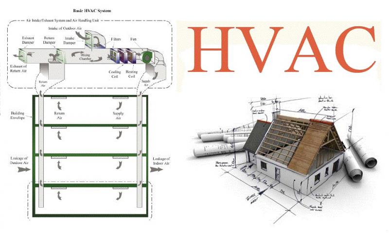
HVAC (stands for Heating, Ventilation and Air Conditioning) equipment needs a control system to regulate the operation of a heating and/or air conditioning system. Usually a sensing device is used to compare the actual state (e.g. temperature) with a target state. Then the control system draws a conclusion what action has to be taken (e.g. start the blower).

The application of Heating, Ventilating, and Air-Conditioning (HVAC) controls starts with an understanding of the building and the use of the spaces to be conditioned and controlled. All control systems operate in accordance with few basic principles but before we discuss these, let’s address few fundamentals of the HVAC system first.

Why Automatic controls?

The capacity of the HVAC system is typically designed for extreme conditions. Most operation is part load/off design as variables such as solar loads, occupancy, ambient temperatures, equipment & lighting loads etc. keep on changing throughout the day. Deviation from design shall result in drastic swings or imbalance since design capacity is greater than the actual load in most operating scenarios. Without control system, the system will become unstable and HVAC would overheat or overcool spaces.

HVAC Systems:

HVAC systems are classified as either self-contained unit packages or as central systems. Unit package describes a single unit that converts a primary energy source (electricity or gas) and provides final heating and cooling to the space to be conditioned. Examples of self-contained unit packages are rooftop HVAC systems, air conditioning units for rooms, and air-to-air heat pumps. With central systems, the primary conversion from fuel such as gas or electricity takes place in a central location, with some form of thermal energy distributed throughout the building or facility. Central systems are a combination of central supply subsystem and multiple end use subsystems.

There are many variations of combined central supply and end use zone systems. The most frequently used combination is central hot and chilled water distributed to multiple fan systems.

The fan systems use water-to-air heat exchangers called coils to provide hot and/or cold air for the controlled spaces. End-use subsystems can be fan systems or terminal units. If the end use subsystems are fan systems, they can be single or multiple zone type.

The multiple end use zone systems are mixing boxes, usually called VAV boxes. Another combination central supply and end use zone system is a central chiller and boiler for the conversion of primary energy, as well as a central fan system to delivery hot and/or cold air.

The typical uses of central systems are in larger, multi-storeyed buildings where access to outside air is more restricted. Typically central systems have lower operating costs but have a complex control sequence.

Where are HVAC controls required?

The HVAC control system is typically distributed across three areas:

  1. The HVAC equipment and their controls located in the main mechanical room. Equipment includes chillers, boiler, hot water generator, heat exchangers, pumps etc.
  2. The weather maker or the “Air Handling Units (AHUs)” may heat, cool, humidify, dehumidify, ventilate, or filter the air and then distribute that air to a section of the building. AHUs are available in various configurations and can be placed in a dedicated room called secondary equipment room or may be located in an open area such as roof top air-handling units.
  3. The individual room controls depending on the HVAC system design. The equipment includes fan coil units, variable air volume systems, terminal reheat, unit ventilators, exhausters, zone temperature/humidistat devices etc.

Benefits of a control system:

Controls are required for one or more of the following reasons:

  1. Maintain thermal comfort conditions
  2. Maintain optimum indoor air quality
  3. Reduce energy use
  4. Safe plant operation
  5. To reduce manpower costs
  6. Identify maintenance problems
  7. Efficient plant operation to match the load
  8. Monitoring system performance

What is control?

In simplest term, the control is defined as the starting, stopping or regulation of heating, ventilating, and air conditioning system. Controlling an HVAC system involves three distinct steps:

  1. Measure a variable and collect data
  2. Process the data with other information
  3. Cause a control action

The above three functions are met through sensor, controller and the controlled device.

Elements of a control system:

HVAC control system, from the simplest room thermostat to the most complicated computerized control, has four basic elements: sensor, controller, controlled device and source of energy.

  1. Sensor measures actual value of controlled variable such as temperature, humidity or flow and provides information to the controller.
  2. Controller receives input from sensor, processes the input and then produces intelligent output signal for controlled device.
  3. Controlled device acts to modify controlled variable as directed by controller.
  4. Source of energy is needed to power the control system. Control systems use either a pneumatic or electric power supply.

Figure below illustrates a basic control loop for room heating. In this example the thermostat assembly contains both the sensor and the controller.

The purpose of this control loop is to maintain the controlled variable (room air temperature) to some desired value, called a setpoint. Heat energy necessary to accomplish the heating is provided by the radiator and the controlled device is the 2-way motorized or solenoid valve, which controls the flow of hot water to the radiator.

room-temperature-control

Panorama offers a wide variety of design solutions for HVAC Controls, including actuators, control panels, control sensors, current sensors and transducers, thermostats, and valves. Contact us for more information on HVAC Controls.

Basic engineering package – Ideal approach

A company contracted for Basic engineering design package adapts it according to the chosen scope of supply work, ranging from the delivery of key equipment to the incorporation of a complete skid-mounted unit.

Only a well qualified & experienced engineering company will be able to successfully execute detail engineering, equipment procurement, preparation of the final plant operating manuals, plant construction etc which ensures a complete delivery cycle of a basic engineering package.

For the delivery of a skid-mounted unit, assembling should take place in fabrication workshops, the documentation should focus more on ways to utilize the unit.
BEP Meetings

The engineering company’s constant contact with the owners of industrial plants is a must during the execution of the basic engineering to ensure:

  • All local conditions and regulations are considered
  • The necessary agreement and understanding on of industrial units chosen technologies is considered.
  • Exchange of information about the actual status during basic engineering performance

Typical meetings:

  • Kick-start meeting to agree on the basic data
  • Intermediate meeting to present & visualize first results and agree on challenges encountered
  • Meeting to present the basic engineering documentation
  • A detail engineering review meeting

Both during and after the execution of a basic engineering project, the engineering company should provide several additional services that are essential to design, construct, install and run the unit.
For example:

  • Supporting documentation for authorities
  • Participating at HAZOP and other safety related meetings
  • Support during commissioning
  • Support during start-up
  • Participation in performance test runs
  • Support for later plant modifications involving issues like de-bottlenecking, capacity increases etc.

Basic engineering package design – Checklist

  • Design Basis
  • Process Description
  • Equipment List
  • Process Flow Diagrams and Heat & Material Balances
  • Piping and Instrumentation Diagrams
  • Process Equipment Data Sheet
  • Instrument List
  • Piping
  • Control Philosophy
  • Effluent stream list

List of vapor emission sources

  • Composition and flow rate of process off gas and evaluation of whether this material can be sent to the hot oil heater or must be sent to a thermal oxidizer.
  • Hot Oil Heater and Steam Generation Boiler characteristics, evaluation of flue gas treating requirements and definition of effluent flue gas treating system requirements
  • Liquid Effluent Streams
  • Solid Waste quantities and type
  • By-product quantities and characteristics

Quality Assurance and Laboratory Information

Utilities Consumption

Panorama’s highly experienced engineers have extensive chemical process engineering expertise in oil and gas, refining, gasification, petrochemical, pharmaceutical and specialty chemicals.