FDA’s role in plant design

If you are involved in any type of manufacturing that is regulated by the FDA, FDA regulatory consulting firms can help you!

FDA consultants (who are all former employees of the FDA or have extensive industry experience) can assist with all phases of the manufacturing process, from single rooms to entire plants, computer systems to manufacturing and processing equipment, design to verifications and validations.

FDA consulting and FDA training services typically include:

  • master and batch record design and reviews
  • specification development (components, in-process, and finished product)
  • supplier audits
  • medical device design history file (21 CFR 820.30)
  • dietary supplements product design
  • equipment verification
  • process validation (prospective validation, retrospective validation, and revalidation)
    • DQ (Design Qualification)
    • IQ (Installation Qualification)
    • OQ (Operational Qualification)
    • PQ (Prospective Qualification)
  • cleaning validation (all industries)
  • GMP (Good Manufacturing Practices) and HACCP (Hazard Analysis and Critical Points)
  • stability studies
  • clean rooms
  • sterility
  • calibration
  • PM (Preventive Maintenance) and DM (Demand Maintenance)
  • plant design
  • computer system development and validation
    • ERP software (Enterprise Resource Planning)
    • data collection and storage systems
    • production equipment
    • system software for manufactured products


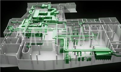
FDA’s role in plant design:

  1. cGMP requirements

    1. Design & Construction features
    2. Lighting
    3. Ventilation, air filtration, air heating and cooling
    4. Plumbing
    5. Sewage & refuse
    6. Washing & Toilet facilities
    7. Sanitation
    8. Maintenance


  1. cGMP Coverage of design
    FDA’s Compliance Programs provide instructions to FDA personnel for conducting activities to evaluate industry compliance with the Federal Food, Drug, and Cosmetic Act and other laws administered by FDA. Compliance Programs are made available to the public under the Freedom of Information Act.
    Compliance Programs do not create or confer any rights for or on any person and do not operate to bind FDA or the public. An alternative approach may be used as long as the approach satisfies the requirements of the applicable statutes and regulations. FDA’s Compliance Programs are organized by the following program areas:

    • Biologics (CBER)
    • Bioresearch Monitoring (BIMO)
    • Devices/Radiological Health (CDRH)
    • Drugs (CDER)
    • Food and Cosmetics (CFSAN)
    • Veterinary Medicine (CVM)


  1. Facilities & Equipment Systems
    • Cleaning & maintenance
    • Facility layout and air handling systems for prevention of cross-contamination (e.g. Penicillin, beta-lactams, steroids, hormones, cytotoxics, etc.)
    • Specifically designed areas for the manufacturing operations performed by the firm to prevent contamination or mix-ups
    • General air handling systems
    • Control system for implementing changes in the building
    • Lighting, potable water, washing and toilet facilities, sewage and refuse disposal
    • Sanitation of the building, use of rodenticides, fungicides, insecticides, cleaning and
    • Sanitizing agents


  1. Preapproval Coverage of Design/Preapproval Inspections/Investigations
    The addition of any new drug to a production environment must be carefully evaluated as to its impact on other products already under production and changes that will be necessary to the building and facility. Construction of new walls, installation of new equipment, and other significant changes must be evaluated for their impact on the overall compliance with GMP requirements.
    For example, new products, such as cephalosporins, would require that the firm demonstrate through appropriate separation and controls that cross-contamination cannot occur with regard to other products being made in the same facility. Also, facilities that may already be operating at full capacity may not have adequate space for additional products


Quality Systems Approach to Pharmaceutical cGMP Regulations

Quality by design means designing and developing a product and associated manufacturing processes that will be used during product development to ensure that the product consistently attains a predefined quality at the end of the manufacturing process.

Quality by design, in conjunction with a quality system, provides a sound framework for the transfer of product knowledge and process understanding from drug development to the commercial manufacturing processes and for post-development changes and optimization.

The CGMP regulations, when viewed in their entirety, incorporate the concept of quality by design. This guidance describes how these elements fit together.

For more information on FDA consulting services for plant design or to schedule a consultation, please contact us.

Continuous Distillation Column Design

Procedure for Continuous Distillation Column Design

Distillation is used to separate components in a feed mixture based upon their relative boiling points. A simple, continuous distillation column can make the separation between two components into two product streams. In multi-component systems, the two main components to be separated are designated as the light and heavy keys. The light key is the more volatile component in greater purity in the top product stream, and the heavy key is the less volatile component in greater purity in the bottom product stream.

Vapor-Liquid Equilibrium

The starting point upon which all column design is based is to accurately determine the relative volatility of the key components to be separated. Using a mass and energy balance simulation program. The user must set up the basis of the simulation by selecting an appropriate fluid package and the components present in the feed. Activity coefficients, estimated by the program or provided by the user, are used to relate non-ideal component interactions.

Column Operating Objectives

The first step in column design is specifying the column operating objectives. These are defined by a primary product composition and an optimal recovery of the product from the waste, recycle or less important by-product stream. These specifications should be in terms of the heavy key impurity in the top stream and the light key impurity in the bottom stream.

Operating Pressure

Once the top and bottom stream compositions are specified, the dew point of the top stream and the boiling point of the bottom stream may be determined at various pressures. An operating pressure should be selected that allows acceptable temperature differences between available utilities because the overhead vapor must be condensed and the bottom liquid reboiled.

When possible, atmospheric or pressure operation of the column is preferred in order to avoid requiring a vacuum system. However, another consideration is component heat sensitivity, which may require lower pressure operation to avoid fouling, product discoloration or decomposition. Often the relative volatility is also improved at lower pressures.

R/Dmin & Nmin and Feed Stage Estimation

Using the simulation program, shortcut procedures based upon total reflux operation allow the minimum reflux ratio (R/Dmin) and minimum number of ideal separation stages (Nmin) to be determined. Using an actual reflux ratio of 1.2 times the minimum reflux ratio will allow an optimal number of stages to be estimated as well as an appropriate feed stage.

Rigorous simulation of the distillation at a given feed rate and composition may now be accomplished by specifying the following: top and bottom product compositions, number of stages, feed stage, and top and bottom pressure.

Parametric cases of this simulation should be used to verify the estimated number of stages and feed location. Add and subtract stages from both the stripping and rectifying section of the column. Do this until the required reflux ratio becomes approximately 1.2 times the minimum reflux ratio, or the trade off between utility usage and the number of stages appears optimal for the specific column. As more total stages are used, the required reboiler duty will decrease until there are diminishing returns.

Diameter and Height of the Column

At this point, the distillation process is well defined, leaving the column diameter and height to be determined. The chosen design case from the simulation program provides the internal liquid and vapor flows and their physical properties for every stage of the column. The column diameter is chosen to provide an acceptable superficial vapor velocity, or “Fs factor”. This is defined as vapor velocity (ft/sec) times square root of vapor density (lb/ft3), and liquid loading defined as volumetric flow rate (gal/min), divided by the cross sectional area of the column (ft2). The column internals can be chosen as either trays or packing. Trayed columns must avoid flooding, weeping and downcomer backup. Packed columns must avoid flooding, minimum surface wetting and mal-distribution.

Project managers should understand and determine these five key design elements for the projects success. Cost, chemical interactions and equipment needs change in a non-linear fashion, as increased output is required. Qualified engineers should consider these critical steps for distillation column design.

Cleanroom

Typically used in manufacturing or scientific research, a cleanroom is a controlled environment that has a low level of pollutants such as dust, airborne microbes, aerosol particles, and chemical vapors. To be exact, a cleanroom has a controlled level of contamination that is specified by the number of particles per cubic meter at a specified particle size. The ambient air outside in a typical city environment contains 35,000,000 particles per cubic meter, 0.5 mm and larger in diameter, corresponding to an ISO 9 cleanroom which is at the lowest level of cleanroom standards.

Cleanroom Overview

Cleanrooms are used in practically every industry where small particles can adversely affect the manufacturing process. They vary in size and complexity, and are used extensively in industries such as semiconductor manufacturing, pharmaceuticals, biotech, medical device and life sciences, as well as critical process manufacturing common in aerospace, optics, military and Department of Energy.

A cleanroom is any given contained space where provisions are made to reduce particulate contamination and control other environmental parameters such as temperature, humidity and pressure. The key component is the High Efficiency Particulate Air (HEPA) filter that is used to trap particles that are 0.3 micron and larger in size. All of the air delivered to a cleanroom passes through HEPA filters, and in some cases where stringent cleanliness performance is necessary; Ultra Low Particulate Air (ULPA) filters are used.

Personnel selected to work in cleanrooms undergo extensive training in contamination control theory. They enter and exit the cleanroom through airlocks, air showers and/or gowning rooms, and they must wear special clothing designed to trap contaminants that are naturally generated by skin and the body.

Depending on the room classification or function, personnel gowning may be as limited as lab coats and hairnets, or as extensive as fully enveloped in multiple layered bunny suits with self-contained breathing apparatus.
Cleanroom clothing is used to prevent substances from being released off the wearer’s body and contaminating the environment. The cleanroom clothing itself must not release particles or fibers to prevent contamination of the environment by personnel. This type of personnel contamination can degrade product performance in the semiconductor and pharmaceutical industries and it can cause cross-infection between medical staff and patients in the healthcare industry for example.

Cleanroom garments include boots, shoes, aprons, beard covers, bouffant caps, coveralls, face masks, frocks/lab coats, gowns, glove and finger cots, hairnets, hoods, sleeves and shoe covers. The type of cleanroom garments used should reflect the cleanroom and product specifications. Low-level cleanrooms may only require special shoes having completely smooth soles that do not track in dust or dirt. However, shoe bottoms must not create slipping hazards since safety always takes precedence. A cleanroom suit is usually required for entering a cleanroom. Class 10,000 cleanrooms may use simple smocks, head covers, and booties. For Class 10 cleanrooms, careful gown wearing procedures with a zipped cover all, boots, gloves and complete respirator enclosure are required.

Cleanroom Air Flow Principles

Cleanrooms maintain particulate-free air through the use of either HEPA or ULPA filters employing laminar or turbulent air flow principles. Laminar, or unidirectional, air flow systems direct filtered air downward in a constant stream. Laminar air flow systems are typically employed across 100% of the ceiling to maintain constant, unidirectional flow. Laminar flow criteria is generally stated in portable work stations (LF hoods), and is mandated in ISO-1 through ISO-4 classified cleanrooms.

Proper cleanroom design encompasses the entire air distribution system, including provisions for adequate, downstream air returns. In vertical flow rooms, this means the use of low wall air returns around the perimeter of the zone. In horizontal flow applications, it requires the use of air returns at the downstream boundary of the process. The use of ceiling mounted air returns is contradictory to proper cleanroom system design.

Graph for Pinch Point Analysis

Pinch Point Analysis

Pinch Point Analysis is a systematic process design methodology consisting of a number of concepts and techniques that ensure an optimal use of energy. The Pinch is characterized by a minimum temperature difference between hot and cold streams and designates the location where the heat recovery is the most constraint.

The fundamental computational tool is the Problem Table algorithm. This tool allows the identifications of the Pinch, as well as of targets for hot and cold utilities.

The net heat flow across Pinch is zero. Consequently, the system can be split into two stand-alone subsystems, above and below the Pinch. Above the Pinch there is need only for hot utility, while below the Pinch only cold utility is necessary. For given ΔTmin the hot and cold utility consumption identified so far becomes Minimum Energy Requirements (MER). No design can achieve MER if there is a cross-pinch heat transfer.

The partition of the original problem in subsystems may introduce redundancy in the number of heat exchangers. When the capital cost is high, it might be necessary to remove the Pinch constraint in order to reduce the number of units. The operation will be paid by supplementary energetic consumption, which has to be optimized against the reduction in capital costs.

The result is that heat recovery problem becomes an optimization of both energy and capital costs, constraint by a minimum temperature approach in designing the heat exchangers. Stream selection and data extraction are essential in Pinch Analysis for effective heat integration.

The key computational assumption in Pinch Point Analysis is constant CP on the interval where the streams are matched. If not, stream segmentation is necessary

The counter-current heat flow of the streams selected for integration may be represented by means of Composite Curves (CC). Another diagram, Grand Composite Curve (GCC) allows the visualization of the excess heat between hot and cold streams against temperature intervals. This feature helps the selection and placement of utilities, as well as the identification of the potential process/process matches.

The synthesis of a Heat Exchanger Network consists of three main activities:

  • Set a reference basis for energy integration, namely:

-Minimum Energy Requirements (MER)

-Utility selection and their placement

-Number of units and heat exchange area

-Cost of energy and hardware at MER

  • Synthesis of heat exchanger network (HEN) for minimum energy requirements and maximum heat recovery. Determine matches in subsystems and generate alternatives.
  • Network optimization. Reduce redundant elements, as small heat exchangers, or small split streams. Find the trade-off between utility consumption, heat exchange area and number of units. Consider constraints

The improvement of design can be realized by Appropriate Placement and Plus/Minus principle. Appropriate Placement defines the optimal location of individual units against the Pinch. It applies to heat engines, heat pumps, distillation columns, evaporators, furnaces, and to any other unit operation that can be represented in terms of heat sources and sinks.

The Plus/Minus principle helps to detect major flow sheet modifications that can improve significantly the energy recovery. Navigating between Appropriate Placement, Plus/Minus Principle and Targeting allows the designer to formulate near-optimum targets for the heat exchanger network, without ever sizing heat exchangers.

Pinch Point principle has been extended to operations involving mass exchange. Saving water can be treated systematically by Water Pinch methodology. Similarly, Hydrogen Pinch can efficiently handle the inventory of hydrogen in refineries. Other applications of industrial interest have been developed in the field of waste and emissions minimization. The systematic methods in handling the integration of mass-exchange operations are still in development. In this area the methods based on optimization techniques are very promising.

Calibration for Pharmaceutical Industries

The pharmaceutical sector is governed by regulatory norms to ensure that quality standards are met for products in line with pharmaceutical cGMP guidelines. The FDA takes food and pharma production very seriously, which is why these guidelines are in place. Calibration is one such process wherein an instrument or a utility system is adjusted so that its readings are adherent to the defined guidelines. It is usually performed as per approved written procedures.
What is Equipment Calibration?
Equipment calibration is important as equipment is often used to gather critical data and hence calibrating them and keeping them up to date becomes mandatory. This process is carried out regularly since equipment used in pharmaceutical manufacturing depending on its functionality is subjected to a lot of wear and tear.Calibration is usually done component-wise to ensure accuracy of the operating equipment as per defined pharmaceutical cGMP.
Types of Calibration
Calibration types are defined as per the parameter which is crucial for a certain process. The classification is largely done on the basis of the type of reading, and common types include:
Pressure Calibration– This method calibrates pressure readings within barometers, transmitters, test gauges and other kinds of equipment commonly used in manufacturing setups.
Temperature Calibration– Calibration is done based on temperature readings, in simulation of a real-time environment. The equipment in this category includes furnaces, weather stations, bio repositories, thermistors, etc.
Flow Calibration– The calibration which is carried out routinely for flow meters that check product quantity or energy functions in processes. Some of the equipment which requires flow calibration includes flowmeters, rotameters and turbine meters.
Pipette Calibration– Pipettes are used in laboratories to measure liquids in small, precise quantities. This calibration method is utilized in labs that make frequent use of pipettes, and is a fairly stringent process since the degree of precision required is very high.
Electrical Calibration– This particular method is used for checking electrical equipment. The accreditation standards are set as per UKAS outlines, since these are considered the most accurate set of standards for electrical calibration.
Mechanical Calibration– Mechanical calibration checks for the accuracy of various measurements such as torque, mass, force, angle and vibration. All these elements are checked in a temperature-controlled facility, since variations in temperature can adversely impact the calibration process.
Since these instruments are used in real-time environments, they are subject to frequent wear and tear. However, they are used in processes that require a lot of precision in terms of data gathering and measured quantities.Therefore, in order to maintain the accuracy of the process and the measurements taken by equipment, frequent calibration is required.

The frequency with which equipment is to be calibrated depends on various factors such as:

  • The importance of the measurements for which instruments are used
  • The defined standards of the equipment manufacturer to adhere to the pharmaceutical CGMP guidelines.
  • The degree of risk involved in the process for which that equipment is being used
  • The degree of precision required from the equipment and the accuracy with which data is to be gathered from the equipment.
  • The extent to which the equipment is stable. This is evaluated from the historical data on the stability of the equipment

Calibration is a mandatory process in the pharmaceutical space considering the need for reproducible product quality. Lack of precision can lead to huge repercussions and penalties. Calibration forms an essential part of the quality assurance and validation process in the pharmaceutical industry.

Validation

Validation Protocols for Pharmaceutical Industries

For pharmaceutical industries, product quality is paramount. Minor inconsistencies can lead to major disasters. To maintain quality assurance, consistency and risk assessment, industries conduct a validation of processes and equipment. A validation is a documented evidence of the consistency of processes and equipment. Design Qualification (DQ), Installation Qualification (IQ), Operational Qualification (OQ) and Performance Qualification (PQ) are an essential part of quality assurance through equipment validation.

DQ IQ OQ PQ protocols are ways of establishing that the equipment which is being used or installed will offer a high degree of quality assurance, so that manufacturing processes will consistently produce products that meet predetermined quality requirements.

Design Qualification (DQ)

Design qualification is a verification process on the design to meet particular requirements relating to the quality of manufacturing and pharmaceutical practices. It is important to take these procedures into consideration and follow them keenly. Along with Process Validation, pharmaceutical manufacturers must conduct Design Qualification during the initial stages. For DQ to be considered whole, other qualifications i.e. IQ, OQ and PQ need to be implemented on each instrument and the system as a whole.

DQ allows manufacturers to make corrections and changes reducing costs and avoiding delays. Changes made to a DQ should be documented which makes DQ on the finalized design easier and less prone to errors. By the use of a design validation protocol it is possible to determine whether the equipment or product will deliver its full functionality and conform to the requirements of the validation master plan.

Installation Qualification (IQ)

Any new equipment is first validated to check if it is capable of producing the desired results through Design Qualification, but its performance in a real-world scenario depends on the installation procedure that follows. Installation Qualification (IQ) verifies that the instrument or equipment being qualified, as well as its sub-systems and any ancillary systems, have been delivered, installed and configured in accordance with the manufacturer’s specifications or installation checklist. All procedures to do with maintenance, cleaning and calibration are drawn at the installation stage. It also details a list of all the continued Good Manufacturing Procedures (cGMP) requirements that are applicable in the installation qualification.

Conformance with cGMP’s requires, that whatever approach is used, it is fully documented in the individual Validation Plan. The IQ should not start with the Factory Acceptance Testing (FAT) or Commissioning tasks, but it should start before these tasks are completed; enabling the validation team to witness and document the final FAT and commissioning testing. The integration of these activities greatly reduces the costly and time consuming replication of unnecessary retesting.

These requirements must all be satisfied before the IQ can be completed and the qualification process is allowed to progress to the execution of the OQ.

Operational Qualification (OQ)

Operational Qualification is an essential process during the development of equipment required in the pharmaceutical industry. OQ is a series of tests which of tests which ensure the equipment and its sub-systems will operate within their specified limits consistently and dependably. Equipment may also be tested during OQ for qualities such as using an expected and acceptable amount of power or maintaining a certain temperature for a predetermined period of time. OQ follows a specific procedure to maintain thoroughness of the tests and accuracy of the results. The protocol must be detailed and easily replicated so that equipment can be tested multiple times using different testers. This ensures that the results are reliable and do not vary from tester to tester. OQ is an important step to develop safe and effective equipment.

Performance Qualification (PQ)

PQ is the final step in qualification processes for equipment, and this step involves verifying and documenting that the equipment is working reproducibly within a specified working range. Rather than testing each instrument individually, they are all tested together as part of a partial or overall process. Before the qualification begins, a detailed test plan is created, based on the process description.

Process Performance Qualification (PPQ) protocol is a vital part of process validation and qualification, which is used to ensure ongoing product quality by documenting performance over a period of time for a certain process.

Equipment qualification through DQ IQ OQ PQ practices is a part of Good Manufacturing Practice (GMP), through which manufacturers and laboratories can ensure that their equipment delivers consistent quality. It reduces the margin for errors, so the product quality can be maintained within industry standards or regulatory authority requirements. When qualification of equipment is not needed very frequently, performing it in-house might not be feasible, so smaller laboratories might benefit from scheduling external equipment validation services on a regular basis instead.

Fire Protection and Safety

Irrespective of its occupancy status, a fire can happen at any time and any place.
Fire has the potential to cause harm to its occupants and severe damage to property. Fire doesn’t only interrupt the whole process of manufacturing and production but also can cause major damage to the building and plant. Much work will be required in order to restore the entire production process.

Successful prevention of fire depends solely on the management who must survey the operation of the business and determine where the loss potential lies.

Inadequately maintained machines can be fire prone. The overheating of bearing, due to insufficient lubrication or the presence of dust, and heat caused by friction are common causes of fire. Frequent inspection and regular maintenance will reduce risk and make the general tidiness of premises easier to achieve.

Major fires start in storage area and warehouses than production areas. Poorly stored goods, even though they are not flammable, may help to spread fire and hinder fire fighters gaining access to the seat of the fire or reduce the effectiveness of sprinkler systems. Goods tidily stored with gangways may help to inhibit the spread of fire.

Fire Safety Audit

Fire has been rated as the 5th largest risk in the Indian Industry. Electrical defaults are the major causes of fire in India. Fire Safety Audit is found to be an effective tool for assessing fire Safety standards of an organization. In other words, it is aimed to assess the building for compliance with the National Building Code of India, relevant Indian Standards and the legislations enacted by State Governments and Local Bodies, on fire prevention, fire protection and life safety measures.

Though fire safety audit is found to be an effective tool for assessing fire safety standards of an occupancy, there is no clear cut provisions in any of the safety legislations in India, regarding the scope, objective, methodology and periodicity of a fire safety audit. Therefore, Fire Safety Audit should be made mandatory for all over India and the work should be entrusted to independent agencies, which have expertise in it. It is reasonable to have a fire safety audit in every year.

Clean agent suppression systems

Clean agent fire suppression systems make the use of inert gases and chemicals in extinguishing a fire.They are also known as gaseous fire suppression. In these systems, fire is suppressed manually or automatically by reducing heat rather than reducing oxygen, reducing fuel or preventing the chain reaction effect of fire. These systems work on a total flooding principle where the agent is applied in a three dimensional method within the enclosed space to deliver a concentrated, highly focused dose of fire suppression.

Clean agent systems are able to suppress fires without causing additional damage unlike water. This drastically reduces the costs incurred for repairs and replacements. This makes these systems the fire suppression systems of choice for commercial and public enterprises that want fast, effective fire suppression that minimizes damage to structures, electronics and other assets.

The agents are non-toxic, they cause no breathing problems for people and won’t obscure vision in an emergency situation.

Automatic Sprinkler Systems

Sprinkler systems are among the most useful tools in firefighting. Automatic sprinklers often are one of the most important fire protection options. The successful application of sprinklers is dependent upon careful design and installation of high quality components by capable engineers and contractors.

A sprinkler system must be installed in compliance with the building’s need. Wet pipe systems offer the greatest degree of reliability and are the most appropriate system type for most heritage fire risks. With the exception of spaces subject to freezing conditions, dry pipe systems do not offer advantages over wet pipe systems in heritage buildings. Preaction sprinkler systems are beneficial in areas of highest water sensitivity. Their success is dependent upon selection of proper suppression and detection components and management’s commitment to properly maintain systems. Water mist represents a very promising alternative to gaseous agent systems.

In India, although there are many rules and regulations, codes and standards related to fire safety they are seldom followed. Laxity in following fire safety measures causes major fires in many buildings. Proper attention must be paid to minimize fire loss because ultimately the community at large has to bear all the losses. There exists large number of different types of firefighting equipment and suppression systems to suit specific requirements. The use of smoke detectors, fire alarms, automatic sprinklers, water mist systems, clean agent suppression system should be encouraged. Above all the success of fire prevention and fire protection mainly depend upon the active co-operation from all personnel.

Detail Engineering Piping Systems

Detailed engineering for piping systems

Detailed engineering are studies which creates a full defined scope of work for every aspect of project development. It is a multi-step process which includes conceptualization, research, feasibility analogy, establishing design requirements, preliminary design plans, detailed designing, production planning and tool design and finally moving towards actual production. Detail engineering studies are a key component for every project development across Mining, Infrastructure, energy, oil&gas sectors.

Detailed engineering companies have the best technical experts & a wide range of experience across various industries to carry out the tasks of project management at the maximum precision level.
Piping engineering is a specialised branch of detailed engineering dealing with design & layouts of piping network along with the Equipments in a process plant.

The images shown form a fully fledged blue print of a plant & are used for plant construction at site. The most important factors to be considered are:

  • Process requirements
  • Process safety
  • Operability
  • Maintenance
  • Compliance with statutory requirements & economy

2

Piping detailed engineering process:

‘Piping’ includes the utility of components such as pipe, valves and fittings. A piping designer or a piping engineering company should be thoroughly acquainted with the equipment, instrumentation and related disciplines. A team of piping detailed engineering consists of Engineers, designers and construction personnel who get together to develop and design piping and instrumentation diagrams also known as P&ID (Process & Instrumentation Diagrams).

However, the process doesn’t stop there, they also make equipment plot plans, define the piping arrangements and make fabrication drawings.
A piping engineering company performs the following processes:

  1. Preparation of plot plan, equipment layouts piping studies, piping specification
  2. Review of process package
  3. Giving inputs to civil, vessel, electrical / instrumentation groups for various purposes

A piping engineering company ideally goes through the following plan of action to initiate the project:

  • Preparation of piping layouts, isometrics, support Drawings
  • Stress analysis
  • Procurement assistance
  • Preparation of drawings for statutory approvals
  • Preview of vendor drawings
  • Coordination with various engineering groups & site

And finally ends with completion & commissioning of plant.

Detail piping engineering: What does it involve?

Detail piping engineering consists of an engineering report for the use of various types of pipes and pumps with pressure drop calculations. It also consists of:

  • Pipes and pumps specifications
  • equipment selection and size
  • instrumentation and process control
  • other piping components such as valves, fittings, piping hangers and supports

Detail piping engineering : How helpful it is to you?

Detail piping engineering focuses on 3 primary pointers:

  • how your piping systems should work;
  • what materials must be used to make the piping structure for the engineering project;
  • select the type of material to be used for certain pipes and piping components

Detailed engineering helps in drafting fabrication and construction specifications. It also helps piping consulting engineers to execute a thermal analysis, vibrating analysis and stress analysis for sound piping layout and implementation.

Basic engineering package – Ideal approach

A company contracted for Basic engineering design package adapts it according to the chosen scope of supply work, ranging from the delivery of key equipment to the incorporation of a complete skid-mounted unit.

Only a well qualified & experienced engineering company will be able to successfully execute detail engineering, equipment procurement, preparation of the final plant operating manuals, plant construction etc which ensures a complete delivery cycle of a basic engineering package.

For the delivery of a skid-mounted unit, assembling should take place in fabrication workshops, the documentation should focus more on ways to utilize the unit.
BEP Meetings

The engineering company’s constant contact with the owners of industrial plants is a must during the execution of the basic engineering to ensure:

  • All local conditions and regulations are considered
  • The necessary agreement and understanding on of industrial units chosen technologies is considered.
  • Exchange of information about the actual status during basic engineering performance

Typical meetings:

  • Kick-start meeting to agree on the basic data
  • Intermediate meeting to present & visualize first results and agree on challenges encountered
  • Meeting to present the basic engineering documentation
  • A detail engineering review meeting

Both during and after the execution of a basic engineering project, the engineering company should provide several additional services that are essential to design, construct, install and run the unit.
For example:

  • Supporting documentation for authorities
  • Participating at HAZOP and other safety related meetings
  • Support during commissioning
  • Support during start-up
  • Participation in performance test runs
  • Support for later plant modifications involving issues like de-bottlenecking, capacity increases etc.

Basic engineering package design – Checklist

  • Design Basis
  • Process Description
  • Equipment List
  • Process Flow Diagrams and Heat & Material Balances
  • Piping and Instrumentation Diagrams
  • Process Equipment Data Sheet
  • Instrument List
  • Piping
  • Control Philosophy
  • Effluent stream list

List of vapor emission sources

  • Composition and flow rate of process off gas and evaluation of whether this material can be sent to the hot oil heater or must be sent to a thermal oxidizer.
  • Hot Oil Heater and Steam Generation Boiler characteristics, evaluation of flue gas treating requirements and definition of effluent flue gas treating system requirements
  • Liquid Effluent Streams
  • Solid Waste quantities and type
  • By-product quantities and characteristics

Quality Assurance and Laboratory Information

Utilities Consumption

Panorama’s highly experienced engineers have extensive chemical process engineering expertise in oil and gas, refining, gasification, petrochemical, pharmaceutical and specialty chemicals.

Pinch analysis & Process integration services

In a highly competitive global economy, maximizing results by eliminating costly inefficiencies is critical.

Chemical & Process Industries in India consume lots of Energy; the primary usage being Heating, Cooling, and Electrical Power.

Traditional attempts to reduce energy only focused on individual piece of equipments & units. Process Integration involves a streamlined & systematic “Total site -as a whole” approach towards use of Heating/Cooling Requirements, electrical power and water. Process Integration ensures maximum advantages by providing alternative designs and structured road maps for long term energy savings.

Though Process Integration covers a wide area, pinch analysis companies & process integration services companies focus mainly in Facilities where Distillation consumes major energy, and where lots of waste energy is available.

Reactions like Nitration, Oxidations and Hydrogenations evolve a lot of heat due to exothermic nature. Typically these reactions, distillation processes or other downstream operations consume considerable amount of heat.

Thus, the concept of having continuous processing of these reactions to utilize the heat evolved in downstream operation integrates the process that can result in significant savings and safe operations.

See how Panorama can help you migrate from batch reactions to continuous ones by piloting the whole process till commercial levels.

Up till now, Process Integration is in use at bigger plants, Panorama’s idea is to make it work in smaller plants as well.

Process Integration Methodology:

  • Generating heat & material balances by optimizing simulation services
  • Performing energy analysis to identify alternatives
  • Make modifications in processing conditions
  • Redesign equipments in the light of above changes.
  • Analyze cost data and finalize proposal.

Waste Heat Recovery Units (WHRU)

The exhaust gas of various processes or even from the exhaust stream of processes & conditioning units generates waste heat which can be used to generate useful heat and reduce fuel consumption.

There are many different commercial recovery units for the transferring of energy from hot medium to cold one:

  • Recuperators
  • Regenerators
  • Heat pipe exchanger
  • Economizers
  • Heat pumps etc

Combined Heat and Power (CHP)

Waste heat of different degrees can be found in final products of certain process or as a by-product in industries like steelmaking plants. Units or devices that could recover the waste heat and transform it into electricity are called CHPs. Such units, for example, use an Organic Rankin Cycle (ORC) with an organic fluid as the working fluid. The fluid has a lower boiling point than water to allow it to boil at low temperature, to for a superheated gas that could drive the blade of a turbine and thus a generator.

Panorama’s offerings

  • Process Integration solutions
  • Energy analysis solutions
  • Batch to Continuous Processing Migration Solutions
  • Waste Heat Recovery -Simple Solutions involving heat recoveries only.
  • Waste Heat Recovery- Comprehensive solutions including CHP (Combined Heat Power)

Panorama maximizes energy efficiency in both initial design and ongoing operations through best practices pinch analysis. Thermal Pinch Analysis & Process Integration is a systematic methodology for determining optimal energy efficiency. In most cases we find millions of dollars of annual operational savings (in facilities more than 15 years old). For Greenfield development we enable process engineers to properly integrate pinch tools into the conceptual process design phase, on which the foundation of the entire lifecycle is built.

For existing facilities, Panorama provides the most effective action plan by understanding complete energy balance for maximum efficiency, identifying suboptimal energy exchange between process streams, and analyzing the most cost effective balance between energy savings and capital expenditure to achieve optimal efficiency.

On short notice, our experts can pull together engineering scopes and feasibility studies to produce ready-to-use initial design work.

Our onsite dedicated teams are available to directly interact with the process specialists, should onsite be preferred to remotely analyzing. Regardless of geography, we use the highest thermodynamic principles to systematically analyze chemical processes and surrounding utility systems.

Panorama’s pinch analysis results in financial savings through better process heat integration.