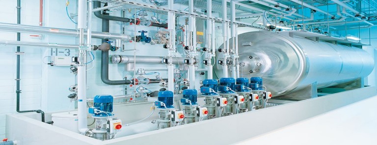
Continuous Distillation Column Design

Procedure for Continuous Distillation Column Design

Distillation is used to separate components in a feed mixture based upon their relative boiling points. A simple, continuous distillation column can make the separation between two components into two product streams. In multi-component systems, the two main components to be separated are designated as the light and heavy keys. The light key is the more volatile component in greater purity in the top product stream, and the heavy key is the less volatile component in greater purity in the bottom product stream.

Vapor-Liquid Equilibrium

The starting point upon which all column design is based is to accurately determine the relative volatility of the key components to be separated. Using a mass and energy balance simulation program. The user must set up the basis of the simulation by selecting an appropriate fluid package and the components present in the feed. Activity coefficients, estimated by the program or provided by the user, are used to relate non-ideal component interactions.

Column Operating Objectives

The first step in column design is specifying the column operating objectives. These are defined by a primary product composition and an optimal recovery of the product from the waste, recycle or less important by-product stream. These specifications should be in terms of the heavy key impurity in the top stream and the light key impurity in the bottom stream.

Operating Pressure

Once the top and bottom stream compositions are specified, the dew point of the top stream and the boiling point of the bottom stream may be determined at various pressures. An operating pressure should be selected that allows acceptable temperature differences between available utilities because the overhead vapor must be condensed and the bottom liquid reboiled.

When possible, atmospheric or pressure operation of the column is preferred in order to avoid requiring a vacuum system. However, another consideration is component heat sensitivity, which may require lower pressure operation to avoid fouling, product discoloration or decomposition. Often the relative volatility is also improved at lower pressures.

R/Dmin & Nmin and Feed Stage Estimation

Using the simulation program, shortcut procedures based upon total reflux operation allow the minimum reflux ratio (R/Dmin) and minimum number of ideal separation stages (Nmin) to be determined. Using an actual reflux ratio of 1.2 times the minimum reflux ratio will allow an optimal number of stages to be estimated as well as an appropriate feed stage.

Rigorous simulation of the distillation at a given feed rate and composition may now be accomplished by specifying the following: top and bottom product compositions, number of stages, feed stage, and top and bottom pressure.

Parametric cases of this simulation should be used to verify the estimated number of stages and feed location. Add and subtract stages from both the stripping and rectifying section of the column. Do this until the required reflux ratio becomes approximately 1.2 times the minimum reflux ratio, or the trade off between utility usage and the number of stages appears optimal for the specific column. As more total stages are used, the required reboiler duty will decrease until there are diminishing returns.

Diameter and Height of the Column

At this point, the distillation process is well defined, leaving the column diameter and height to be determined. The chosen design case from the simulation program provides the internal liquid and vapor flows and their physical properties for every stage of the column. The column diameter is chosen to provide an acceptable superficial vapor velocity, or “Fs factor”. This is defined as vapor velocity (ft/sec) times square root of vapor density (lb/ft3), and liquid loading defined as volumetric flow rate (gal/min), divided by the cross sectional area of the column (ft2). The column internals can be chosen as either trays or packing. Trayed columns must avoid flooding, weeping and downcomer backup. Packed columns must avoid flooding, minimum surface wetting and mal-distribution.

Project managers should understand and determine these five key design elements for the projects success. Cost, chemical interactions and equipment needs change in a non-linear fashion, as increased output is required. Qualified engineers should consider these critical steps for distillation column design.

RO/DI Water Systems

RO/DI Water Systems

RO/DI stands for Reverse Osmosis and Deionization. The product is a multi-stage water filter, which takes in ordinary tap water and produces highly purified water.

Tap water often contains impurities that can cause problems. These may include phosphates, nitrates, chlorine, and various heavy metals. Excessive phosphate and nitrate levels can cause an algae bloom. Copper is often present in tap water due to leaching from pipes and is highly toxic to invertebrates. An RO/DI filter removes practically all of these impurities.

There are typically four stages in a RO/DI filter:

  • Sediment filter
  • Carbon block
  • Reverse osmosis membrane
  • Deionization resin

If there are less than four stages, something was left out. If there are more, something was duplicated.

The sediment filter, typically a foam block, removes particles from the water. Its purpose is to prevent clogging of the carbon block and RO membrane. Good sediment filters will remove particles down to one micron or smaller.

The carbon, typically a block of powdered activated carbon, filters out smaller particles, adsorbs some dissolved compounds, and deactivates chlorine. The latter is the most important part: free chlorine in the water will destroy the RO membrane.

The RO membrane is a semi-permeable thin film. Water under pressure is forced through it. Molecules larger/heavier than water (which is very small/light) penetrate the membrane less easily and tend to be left behind.

The DI resin exchanges the remaining ions, removing them from the solution.

There are three types of RO membrane on the market:

  • Cellulose Triacetate (CTA)
  • Thin Film Composite (TFC)
  • Poly-Vinyl Chloride (PVC)

The difference between the three concerns how they are affected by chlorine: CTA membranes require chlorine in the water to prevent them from rotting. TFC membranes are damaged by chlorine and must be protected from it. PVC membranes are impervious to both chlorine and bacteria.

Reverse osmosis typically removes 90-98% of all the impurities of significance to the aquarist. If that is good enough for your needs, then you don’t need the DI stage. The use of RO by itself is certainly better than plain tap water and, in many cases, is perfectly adequate.

RO by itself might not be adequate if your tap water contains something that you want to reduce by more than 90-98%.

A DI stage by itself, without the other filter stages, will produce water that is pretty much free of dissolved solids. However, DI resin is fairly expensive and will last only about 1/20th as long when used without additional filtration. If you’re only going to buy either a RO or a DI, it would be best to choose the RO, unless you only need small amounts of purified water.

Duplicating stages can extend their life and improve their efficiency. For example, if you have two DI stages in series, one can be replaced when it’s exhausted without producing any impure water. If you have both a 5-micron sediment filter and a 1-micron filter, they will take longer to clog up. If there are two carbon stages, there will be less chlorine attacking the TFC membrane. Whether the extra stages are worth the extra money is largely a matter of circumstance and opinion.

RO/DI capacities are measured in gallons per day (GPD), and typically fall within the 25-100 GPD range. The main difference between these units is the size of the RO membrane. Other differences are (a) the flow restrictor that determines how much waste water is produced, (b) the water gets less contact time in the carbon and DI stages in high-GPD units than low-GPD units, and (c) units larger than 35 GPD typically have welded-together membranes.

As a result of the membrane welding and the reduced carbon contact time, RO membranes larger than 35 GPD produce water that is slightly less pure. This primarily affects the life of the DI resin.

Most aquarists won’t use more than 25 GPD averaged over time. If you have a decent size storage container, that size should be adequate. A higher GPD rating comes in handy, however, when filling a large tank for the first time or in emergencies when you need a lot of water in a hurry.

The advertised GPD values assume ideal conditions, notably optimum water pressure and temperature. The purity of your tap water also affects it. In other words, your mileage will vary.

An RO filter has two outputs: purified water and wastewater. A well-designed unit will have about 4X as much wastewater as purified water. The idea is that the impurities that don’t go through the membrane get flushed out with the wastewater.

There is nothing particularly wrong with the wastewater except for a slightly elevated dissolved solid content. It may actually be cleaner than your tap water because of the sediment and carbon filters. Feel free to water your plants with it.

Cleanroom

Typically used in manufacturing or scientific research, a cleanroom is a controlled environment that has a low level of pollutants such as dust, airborne microbes, aerosol particles, and chemical vapors. To be exact, a cleanroom has a controlled level of contamination that is specified by the number of particles per cubic meter at a specified particle size. The ambient air outside in a typical city environment contains 35,000,000 particles per cubic meter, 0.5 mm and larger in diameter, corresponding to an ISO 9 cleanroom which is at the lowest level of cleanroom standards.

Cleanroom Overview

Cleanrooms are used in practically every industry where small particles can adversely affect the manufacturing process. They vary in size and complexity, and are used extensively in industries such as semiconductor manufacturing, pharmaceuticals, biotech, medical device and life sciences, as well as critical process manufacturing common in aerospace, optics, military and Department of Energy.

A cleanroom is any given contained space where provisions are made to reduce particulate contamination and control other environmental parameters such as temperature, humidity and pressure. The key component is the High Efficiency Particulate Air (HEPA) filter that is used to trap particles that are 0.3 micron and larger in size. All of the air delivered to a cleanroom passes through HEPA filters, and in some cases where stringent cleanliness performance is necessary; Ultra Low Particulate Air (ULPA) filters are used.

Personnel selected to work in cleanrooms undergo extensive training in contamination control theory. They enter and exit the cleanroom through airlocks, air showers and/or gowning rooms, and they must wear special clothing designed to trap contaminants that are naturally generated by skin and the body.

Depending on the room classification or function, personnel gowning may be as limited as lab coats and hairnets, or as extensive as fully enveloped in multiple layered bunny suits with self-contained breathing apparatus.
Cleanroom clothing is used to prevent substances from being released off the wearer’s body and contaminating the environment. The cleanroom clothing itself must not release particles or fibers to prevent contamination of the environment by personnel. This type of personnel contamination can degrade product performance in the semiconductor and pharmaceutical industries and it can cause cross-infection between medical staff and patients in the healthcare industry for example.

Cleanroom garments include boots, shoes, aprons, beard covers, bouffant caps, coveralls, face masks, frocks/lab coats, gowns, glove and finger cots, hairnets, hoods, sleeves and shoe covers. The type of cleanroom garments used should reflect the cleanroom and product specifications. Low-level cleanrooms may only require special shoes having completely smooth soles that do not track in dust or dirt. However, shoe bottoms must not create slipping hazards since safety always takes precedence. A cleanroom suit is usually required for entering a cleanroom. Class 10,000 cleanrooms may use simple smocks, head covers, and booties. For Class 10 cleanrooms, careful gown wearing procedures with a zipped cover all, boots, gloves and complete respirator enclosure are required.

Cleanroom Air Flow Principles

Cleanrooms maintain particulate-free air through the use of either HEPA or ULPA filters employing laminar or turbulent air flow principles. Laminar, or unidirectional, air flow systems direct filtered air downward in a constant stream. Laminar air flow systems are typically employed across 100% of the ceiling to maintain constant, unidirectional flow. Laminar flow criteria is generally stated in portable work stations (LF hoods), and is mandated in ISO-1 through ISO-4 classified cleanrooms.

Proper cleanroom design encompasses the entire air distribution system, including provisions for adequate, downstream air returns. In vertical flow rooms, this means the use of low wall air returns around the perimeter of the zone. In horizontal flow applications, it requires the use of air returns at the downstream boundary of the process. The use of ceiling mounted air returns is contradictory to proper cleanroom system design.

RESOURCE OPTIMIZATION

In today’s industrial age, where manufacturing processes are highly crucial and a synonym of development and growth, the need to use resources effectively and efficiently has become necessary. The continuous growth of industries has led to development of highly efficient or leaner processes which focus on minimum wastage and maximum utilization of the available resources through various technologies developed overtime. The use of robots and automating the processes in order to eliminate human error and increase efficiency has been adopted by almost every industry today which has further been facilitated by the Internet of Things (I0T) in developing smarter processes.

Utility optimization not only consists of handling resources in a smart manner, but also optimizing the path or manner in which they are handled. Adjusting the placement of machines as well as defining the flow of resources throughout the shop floor is also an integral part of the utility optimization process. An efficient flow ensures an efficient execution of process and minimum wastage of time and resources. This is usually done through the use of process flow charts do determine process steps as well as Pareto charts to determine the importance of every resource in terms of its usage and need in every process.

In order to execute resource optimization and make sure that it is continuously being carried out, energy audits and water audits can be done which track the energy needs of an organization and track the water consumption by the organization respectively. The audits not only provide feedback about the status of optimization within the organization, but also help in tracking the development in this area and accordingly set targets. Even though these audits are a bit time consuming but they are highly necessary as they help the organization stay aligned with their set targets.

Optimization of resource usage not only decreases the amount of waste generated, but also leads to greater profits and creates opportunities for recycling and reusing the wasted resources. In a lot of cases, resource optimization leads to a reduction in carbon footprint which is vital due to the currently degrading environmental conditions. Since India agreed to ratify the second commitment period (2013-2020) of the 1997 Kyoto Protocol for the reduction of Greenhouse Gases and thus reduce the carbon footprint, the need for cutting emissions and correspondingly minimizing waste through resource optimization has gained more importance. The rising trend of green technologies has facilitated in optimization as well as cutting down on energy usage and reducing emissions.

The whole world is currently progressing at an unbelievable rate and the environment is getting affected due to that very progress Resource optimization, hence, has become necessary not only for generating greater profits and minimizing wastage of resources, but also for sustainability.  “Recycle and Reuse” has become the motto for every major organization and new ways to optimize resource usage are constantly being researched and put into use. Since the progression of technology is inevitable, there will always be a great need for effective resource optimization processes which contribute to both- organization’s profits as well as sustainability.

Calibration for Pharmaceutical Industries

The pharmaceutical sector is governed by regulatory norms to ensure that quality standards are met for products in line with pharmaceutical cGMP guidelines. The FDA takes food and pharma production very seriously, which is why these guidelines are in place. Calibration is one such process wherein an instrument or a utility system is adjusted so that its readings are adherent to the defined guidelines. It is usually performed as per approved written procedures.
What is Equipment Calibration?
Equipment calibration is important as equipment is often used to gather critical data and hence calibrating them and keeping them up to date becomes mandatory. This process is carried out regularly since equipment used in pharmaceutical manufacturing depending on its functionality is subjected to a lot of wear and tear.Calibration is usually done component-wise to ensure accuracy of the operating equipment as per defined pharmaceutical cGMP.
Types of Calibration
Calibration types are defined as per the parameter which is crucial for a certain process. The classification is largely done on the basis of the type of reading, and common types include:
Pressure Calibration– This method calibrates pressure readings within barometers, transmitters, test gauges and other kinds of equipment commonly used in manufacturing setups.
Temperature Calibration– Calibration is done based on temperature readings, in simulation of a real-time environment. The equipment in this category includes furnaces, weather stations, bio repositories, thermistors, etc.
Flow Calibration– The calibration which is carried out routinely for flow meters that check product quantity or energy functions in processes. Some of the equipment which requires flow calibration includes flowmeters, rotameters and turbine meters.
Pipette Calibration– Pipettes are used in laboratories to measure liquids in small, precise quantities. This calibration method is utilized in labs that make frequent use of pipettes, and is a fairly stringent process since the degree of precision required is very high.
Electrical Calibration– This particular method is used for checking electrical equipment. The accreditation standards are set as per UKAS outlines, since these are considered the most accurate set of standards for electrical calibration.
Mechanical Calibration– Mechanical calibration checks for the accuracy of various measurements such as torque, mass, force, angle and vibration. All these elements are checked in a temperature-controlled facility, since variations in temperature can adversely impact the calibration process.
Since these instruments are used in real-time environments, they are subject to frequent wear and tear. However, they are used in processes that require a lot of precision in terms of data gathering and measured quantities.Therefore, in order to maintain the accuracy of the process and the measurements taken by equipment, frequent calibration is required.

The frequency with which equipment is to be calibrated depends on various factors such as:

  • The importance of the measurements for which instruments are used
  • The defined standards of the equipment manufacturer to adhere to the pharmaceutical CGMP guidelines.
  • The degree of risk involved in the process for which that equipment is being used
  • The degree of precision required from the equipment and the accuracy with which data is to be gathered from the equipment.
  • The extent to which the equipment is stable. This is evaluated from the historical data on the stability of the equipment

Calibration is a mandatory process in the pharmaceutical space considering the need for reproducible product quality. Lack of precision can lead to huge repercussions and penalties. Calibration forms an essential part of the quality assurance and validation process in the pharmaceutical industry.

Utility Systems Qualification – Backbone for the Pharmaceutical Industry

Pharmaceutical manufacturing is a highly regulated industry. Given the stress on product quality and the widespread impact of substandard production on public health and safety, utility system qualification is a critical step that companies must take towards ensuring that all their products comply with federal laws and regulations.

In pharmaceuticals, critical utilities like WFI, RODI, Compressed Air, Nitrogen, Air Handling Units (AHU) and HVAC (Heating, Ventilation and Air Conditioning) systems support the manufacturing process. As a result, these are treated as products that need to satisfy FDA regulatory requirements and pharmaceutical manufacturing standards, just like raw materials and other equipment used in the industry.

Quantitative and qualitative specifications: Utilities must pass a string of qualitative and quantitative specifications to be considered satisfactory. Different utility systems have different quality and standard criteria, designed on the basis of inputs from relevant departments and organizations as well as manufacturing and engineering provisions. When a validation program is set in place for utility systems used in pharmaceutical, critical utilities should be first on the list. It’s important to focus on the design, qualification and monitoring of each utility system used in pharmaceutical or biotech companies, so their end product fulfills all pharmaceutical quality standards.

cGMP and FDA guidelines: Utility system qualification is designed to ensure that utilities in use conform to health and safety regulations, as well as pharmaceutical manufacturing standards and cGMP guidelines. Current good manufacturing practices (cGMPs) are FDA guidelines that check the design, control and monitoring of manufacturing facilities and processes. To comply with cGMP regulations, drugs and medicinal products need to be of the right quality, strength and purity, by way of adequately controlled and monitored manufacturing operations.

Steps in utility system qualification include:

  • Implementing strong operating procedures
  • Establishing extensive quality control systems
  • Procuring a consistent quality of raw material supplies
  • Maintaining dependable testing labs

If such a broad control system is implemented in a pharmaceutical facility, it can help to control:

  • Instances of mix-ups
  • Contamination, errors
  • Defects and deviations during the manufacturing process

Such pharmaceutical products are better able to meet public health and safety laws established by the FDA.

Flexibility: Pharmaceutical cGMP guidelines are flexible enough that all manufacturers are free to decide how to apply FDA controls in ways that fit their unique requirements. They can make use of a variety of processing methods, testing procedures and scientific designs to adapt their manufacturing processes to meet the laws. Because of the flexibility of these laws, companies can use innovative approaches and sophisticated technology to implement a system of continual improvement in order to achieve a consistent quality of pharmaceutical supplies.

FDA approved regulations: All pharmaceutical manufacturing facilities need to adhere strictly to FDA-approved regulations. Failure to meet FDA regulations can result in responsive action by the authorities against the product or the responsible facility, depending upon the seriousness of non-compliance. The company may have to recall the product under orders of the FDA, to ensure it does not cause additional harm or risk to the public.

cGMP requirements can be useful in ensuring the efficacy, quality and safety of pharmaceutical products by making sure facilities are in good operating condition, with sufficiently calibrated and well-maintained equipment, trained and experienced staff and reliable and efficient processes.

While a utility system cannot affect product quality on its own, it forms an integral part of the manufacturing process. That is where Panorama Consulting and Engineering, Inc. helps the companies setting up the validation processes as per the regulatory requirements.