Design For Safety Equipment and design

Design for safety

System safety

System Safety is the application of engineering and management principles, criteria, and techniques to optimize all aspects of safety within the constraints of operational effectiveness, time, and cost throughout all phases of the system life cycle. It is a planned, disciplined and systematic approach to preventing or reducing accidents throughout the lifecycle of a system

Primary concern is the management of risks through:

  • Risk identification, evaluation, elimination & control through analysis, design & management

History of system safety

Design Safety arose in the 1950s after dissatisfaction with the fly-fix-fly approach to safety. Design Safety was first adopted by the US Air Force. It led to the development of mil-std-882 Standard Practice for System Safety (v1 1960s). The basic concept of System was rather than assigning a safety engineer to demonstrate that a design is safe, safety considerations were to be integrated from the design phase of the project.

Founding principles

Safety should be designed in

  • Critical reviews of the system design identify hazards that can be controlled by modifying the design
  • Modifications are most readily accepted during the early stages of design, development, and test
  • Previous design deficiencies can be corrected to prevent their recurrence

Inherent safety requires both engineering and management techniques to control the hazards of a system

  • A safety program must be planned and implemented such that safety analyses are integrated with other factors that impact management decisions

Safety requirements must be consistent with other program or design requirements

  • The evolution of a system design is a series of tradeoffs among competing disciplines to optimize relative contributions
  • Safety competes with other disciplines; it does not override them

The main principles of Safe design are:

  • Inherent safety
  • Safety factors
  • Multiple independent safety barriers

Inherently safe design 

Inherent: belonging to the very nature of the person/thing (inseparable). It is recommended that Inherent safe design should be the first step in safety engineering. Change the process to eliminate hazards, rather than accepting the hazards and developing add-on features to control them, unlike engineered features, inherent safety cannot be compromised.

Minimize inherent dangers as far as possible by considering the following:

  • Potential hazards are excluded rather than just enclosed or managed
  • Replace dangerous substances or reactions by less dangerous ones (instead of encapsulating the process)
  • Use fireproof materials instead of flammable ones (better than using flammable materials but keeping temperatures low)
  • Perform reactions at low temperatures & pressures instead of building resistant vessels

Safety Factors

Factors of safety (FoS), also known as safety factor (SF), is a term describing the load carrying capacity of a system beyond the expected or actual loads. Essentially, the factor of safety is how much stronger the system is than it usually needs to be for an intended load. Safety factors are often calculated using detailed analysis because comprehensive testing is impractical on many projects, such as bridges and buildings, but the structure’s ability to carry load must be determined to a reasonable accuracy.

When the material used is under strength, factor of safety covers uncertainties in material strength. It covers poor workmanship. It also covers unexpected behavior of the structure and natural disasters. Stresses are produced which may be very high. Factor of safety may take care of these loads during construction. Presence of residual stresses and stress concentrations beyond the level theoretically expected.

Multiple Independent Safety Barriers

Safety barriers are arranged in chains. The aim is to make each barrier independent of its predecessors so that if the first fails, then the second is still intact, etc. Typically, the first barriers are measures to prevent an accident, after which follow barriers that limit the consequences of an accident, and, finally, rescue services as the last resort.

The basic idea behind multiple barriers is that even if the first barrier is well constructed, it may fail, due to unforeseen reason, and that the second barrier should then provide protection. The major problem in the construction of safety barriers is how to make them as independent of each other as possible. If two or more barriers are sensitive to the same type of impact, then one and the same destructive force can get rid of all of them in one swoop.

These three principles of engineering safety – inherent safety, safety factors, and multiple barriers are quite different in nature, but they have one important trait in common. They all aim at protecting us not only against risks that can be assigned meaningful probability estimates, but also against dangers that cannot be probabilized, such as the possibility that some unforeseen even triggers a hazard that is seemingly under control. It remains, however, to investigate more in detail the principles underlying safety engineering and, not least, to clarify how they relate to other principles of engineering design.


Ten reasons why your project requires an MEP Consulting Firm

Any project is successful when the right team works on it. For any construction or renovation project an MEP consulting firm is just as important as an architect or a builder. MEP stands for Mechanical, Electrical and Plumbing; a type of engineering that focuses on creating a safe environment for human use.
There are various reasons why MEP consultants are highly important for any building project.

We’ve listed down the top ten reasons.

  1. Mechanical – For any building project, residential or commercial, heating and ventilation services are essential. This is where the MEP engineers step in. They are responsible for the installation and maintenance of air conditioners, heaters, exhaust and smoke control. An MEP consultant will ensure their designs provide comfort and run efficiently.
  2. Electrical – Electrical services are indispensable. Your project will be incomplete without electricity and lighting. MEP consultants are responsible not just for lighting but also other electrical services such as fire alarms, security systems, smoke alarms etc. They provide solutions to the best services that are energy efficient and environment friendly.
  3. Plumbing–The plumbing aspect focuses on fire suppression systems as well as gas delivery systems in medical and laboratory settings. They are also responsible for water and waste management systems such as drinking water, irrigation water, sewers etc.
  4. Effective design – MEP consultants provide the best design solutions that are cost effective and worthwhile in the long run. These designs should not only employ the most recent and competent technologies but also provide foresight to ensure maximum lifecycle.
  5. Environment friendly – Whether it is energy conservation or water conservation, the experts certainly know the best. These consultants aim at providing services that utilize environment friendly products in order to reduce excessive consumption of resources.
  6. Cost Efficient – Every project that you take up has a stipulated budget that needs to be followed. With the help of MEP engineers not only do you manage to stay inside budget but also end up with systems that will be cost efficient in the long run.
  7. Optimum use–The expertise of MEP engineersensures that the products and systems required for your project provide maximum utilization. They ensure that maintenance of systems is limited and simple and workers are well trained to handle issues, if any.
  8. . Indoor environment –While focusing on creating an ecofriendly environment for the outdoors, it is also vital to build a safe and healthy environment indoors. Indoor environment quality refers to the use of natural daylight, moisture control, optimizing systems etc. A healthy indoor environment equates a safer environment for everyone.
  9. Building mechanism –Every system is connected to centralized hardware and software networks that control the indoor and outdoor features in a building. For example, your construction project requires HVAC commissioning; MEP consultants will cover the entire procedure for the project. Automation systems are required to build and maintain a building’s optimal operational performance and ensure safety and comfort the occupants.
  10. Expertise- It is always better to leave the job in the hands of the one that knows the best. MEP consultants are highly trained and experienced in their field. They work closely with architects and owners to provide successful coordination of building systems.

Panorama offers a variety of services in the mechanical, electrical and plumbing divisions for pharmaceutical and chemical sectors. Our specialized services will help your company with the sustenance it requires. We are a leading MEP Consulting Firm in Mumbai with numerous successful projects.

FDA’s role in plant design

If you are involved in any type of manufacturing that is regulated by the FDA, FDA regulatory consulting firms can help you!

FDA consultants (who are all former employees of the FDA or have extensive industry experience) can assist with all phases of the manufacturing process, from single rooms to entire plants, computer systems to manufacturing and processing equipment, design to verifications and validations.

FDA consulting and FDA training services typically include:

  • master and batch record design and reviews
  • specification development (components, in-process, and finished product)
  • supplier audits
  • medical device design history file (21 CFR 820.30)
  • dietary supplements product design
  • equipment verification
  • process validation (prospective validation, retrospective validation, and revalidation)
    • DQ (Design Qualification)
    • IQ (Installation Qualification)
    • OQ (Operational Qualification)
    • PQ (Prospective Qualification)
  • cleaning validation (all industries)
  • GMP (Good Manufacturing Practices) and HACCP (Hazard Analysis and Critical Points)
  • stability studies
  • clean rooms
  • sterility
  • calibration
  • PM (Preventive Maintenance) and DM (Demand Maintenance)
  • plant design
  • computer system development and validation
    • ERP software (Enterprise Resource Planning)
    • data collection and storage systems
    • production equipment
    • system software for manufactured products


FDA’s role in plant design:

  1. cGMP requirements

    1. Design & Construction features
    2. Lighting
    3. Ventilation, air filtration, air heating and cooling
    4. Plumbing
    5. Sewage & refuse
    6. Washing & Toilet facilities
    7. Sanitation
    8. Maintenance


  1. cGMP Coverage of design
    FDA’s Compliance Programs provide instructions to FDA personnel for conducting activities to evaluate industry compliance with the Federal Food, Drug, and Cosmetic Act and other laws administered by FDA. Compliance Programs are made available to the public under the Freedom of Information Act.
    Compliance Programs do not create or confer any rights for or on any person and do not operate to bind FDA or the public. An alternative approach may be used as long as the approach satisfies the requirements of the applicable statutes and regulations. FDA’s Compliance Programs are organized by the following program areas:

    • Biologics (CBER)
    • Bioresearch Monitoring (BIMO)
    • Devices/Radiological Health (CDRH)
    • Drugs (CDER)
    • Food and Cosmetics (CFSAN)
    • Veterinary Medicine (CVM)


  1. Facilities & Equipment Systems
    • Cleaning & maintenance
    • Facility layout and air handling systems for prevention of cross-contamination (e.g. Penicillin, beta-lactams, steroids, hormones, cytotoxics, etc.)
    • Specifically designed areas for the manufacturing operations performed by the firm to prevent contamination or mix-ups
    • General air handling systems
    • Control system for implementing changes in the building
    • Lighting, potable water, washing and toilet facilities, sewage and refuse disposal
    • Sanitation of the building, use of rodenticides, fungicides, insecticides, cleaning and
    • Sanitizing agents


  1. Preapproval Coverage of Design/Preapproval Inspections/Investigations
    The addition of any new drug to a production environment must be carefully evaluated as to its impact on other products already under production and changes that will be necessary to the building and facility. Construction of new walls, installation of new equipment, and other significant changes must be evaluated for their impact on the overall compliance with GMP requirements.
    For example, new products, such as cephalosporins, would require that the firm demonstrate through appropriate separation and controls that cross-contamination cannot occur with regard to other products being made in the same facility. Also, facilities that may already be operating at full capacity may not have adequate space for additional products


Quality Systems Approach to Pharmaceutical cGMP Regulations

Quality by design means designing and developing a product and associated manufacturing processes that will be used during product development to ensure that the product consistently attains a predefined quality at the end of the manufacturing process.

Quality by design, in conjunction with a quality system, provides a sound framework for the transfer of product knowledge and process understanding from drug development to the commercial manufacturing processes and for post-development changes and optimization.

The CGMP regulations, when viewed in their entirety, incorporate the concept of quality by design. This guidance describes how these elements fit together.

For more information on FDA consulting services for plant design or to schedule a consultation, please contact us.

Continuous Distillation Column Design

Procedure for Continuous Distillation Column Design

Distillation is used to separate components in a feed mixture based upon their relative boiling points. A simple, continuous distillation column can make the separation between two components into two product streams. In multi-component systems, the two main components to be separated are designated as the light and heavy keys. The light key is the more volatile component in greater purity in the top product stream, and the heavy key is the less volatile component in greater purity in the bottom product stream.

Vapor-Liquid Equilibrium

The starting point upon which all column design is based is to accurately determine the relative volatility of the key components to be separated. Using a mass and energy balance simulation program. The user must set up the basis of the simulation by selecting an appropriate fluid package and the components present in the feed. Activity coefficients, estimated by the program or provided by the user, are used to relate non-ideal component interactions.

Column Operating Objectives

The first step in column design is specifying the column operating objectives. These are defined by a primary product composition and an optimal recovery of the product from the waste, recycle or less important by-product stream. These specifications should be in terms of the heavy key impurity in the top stream and the light key impurity in the bottom stream.

Operating Pressure

Once the top and bottom stream compositions are specified, the dew point of the top stream and the boiling point of the bottom stream may be determined at various pressures. An operating pressure should be selected that allows acceptable temperature differences between available utilities because the overhead vapor must be condensed and the bottom liquid reboiled.

When possible, atmospheric or pressure operation of the column is preferred in order to avoid requiring a vacuum system. However, another consideration is component heat sensitivity, which may require lower pressure operation to avoid fouling, product discoloration or decomposition. Often the relative volatility is also improved at lower pressures.

R/Dmin & Nmin and Feed Stage Estimation

Using the simulation program, shortcut procedures based upon total reflux operation allow the minimum reflux ratio (R/Dmin) and minimum number of ideal separation stages (Nmin) to be determined. Using an actual reflux ratio of 1.2 times the minimum reflux ratio will allow an optimal number of stages to be estimated as well as an appropriate feed stage.

Rigorous simulation of the distillation at a given feed rate and composition may now be accomplished by specifying the following: top and bottom product compositions, number of stages, feed stage, and top and bottom pressure.

Parametric cases of this simulation should be used to verify the estimated number of stages and feed location. Add and subtract stages from both the stripping and rectifying section of the column. Do this until the required reflux ratio becomes approximately 1.2 times the minimum reflux ratio, or the trade off between utility usage and the number of stages appears optimal for the specific column. As more total stages are used, the required reboiler duty will decrease until there are diminishing returns.

Diameter and Height of the Column

At this point, the distillation process is well defined, leaving the column diameter and height to be determined. The chosen design case from the simulation program provides the internal liquid and vapor flows and their physical properties for every stage of the column. The column diameter is chosen to provide an acceptable superficial vapor velocity, or “Fs factor”. This is defined as vapor velocity (ft/sec) times square root of vapor density (lb/ft3), and liquid loading defined as volumetric flow rate (gal/min), divided by the cross sectional area of the column (ft2). The column internals can be chosen as either trays or packing. Trayed columns must avoid flooding, weeping and downcomer backup. Packed columns must avoid flooding, minimum surface wetting and mal-distribution.

Project managers should understand and determine these five key design elements for the projects success. Cost, chemical interactions and equipment needs change in a non-linear fashion, as increased output is required. Qualified engineers should consider these critical steps for distillation column design.

RO/DI Water Systems

RO/DI Water Systems

RO/DI stands for Reverse Osmosis and Deionization. The product is a multi-stage water filter, which takes in ordinary tap water and produces highly purified water.

Tap water often contains impurities that can cause problems. These may include phosphates, nitrates, chlorine, and various heavy metals. Excessive phosphate and nitrate levels can cause an algae bloom. Copper is often present in tap water due to leaching from pipes and is highly toxic to invertebrates. An RO/DI filter removes practically all of these impurities.

There are typically four stages in a RO/DI filter:

  • Sediment filter
  • Carbon block
  • Reverse osmosis membrane
  • Deionization resin

If there are less than four stages, something was left out. If there are more, something was duplicated.

The sediment filter, typically a foam block, removes particles from the water. Its purpose is to prevent clogging of the carbon block and RO membrane. Good sediment filters will remove particles down to one micron or smaller.

The carbon, typically a block of powdered activated carbon, filters out smaller particles, adsorbs some dissolved compounds, and deactivates chlorine. The latter is the most important part: free chlorine in the water will destroy the RO membrane.

The RO membrane is a semi-permeable thin film. Water under pressure is forced through it. Molecules larger/heavier than water (which is very small/light) penetrate the membrane less easily and tend to be left behind.

The DI resin exchanges the remaining ions, removing them from the solution.

There are three types of RO membrane on the market:

  • Cellulose Triacetate (CTA)
  • Thin Film Composite (TFC)
  • Poly-Vinyl Chloride (PVC)

The difference between the three concerns how they are affected by chlorine: CTA membranes require chlorine in the water to prevent them from rotting. TFC membranes are damaged by chlorine and must be protected from it. PVC membranes are impervious to both chlorine and bacteria.

Reverse osmosis typically removes 90-98% of all the impurities of significance to the aquarist. If that is good enough for your needs, then you don’t need the DI stage. The use of RO by itself is certainly better than plain tap water and, in many cases, is perfectly adequate.

RO by itself might not be adequate if your tap water contains something that you want to reduce by more than 90-98%.

A DI stage by itself, without the other filter stages, will produce water that is pretty much free of dissolved solids. However, DI resin is fairly expensive and will last only about 1/20th as long when used without additional filtration. If you’re only going to buy either a RO or a DI, it would be best to choose the RO, unless you only need small amounts of purified water.

Duplicating stages can extend their life and improve their efficiency. For example, if you have two DI stages in series, one can be replaced when it’s exhausted without producing any impure water. If you have both a 5-micron sediment filter and a 1-micron filter, they will take longer to clog up. If there are two carbon stages, there will be less chlorine attacking the TFC membrane. Whether the extra stages are worth the extra money is largely a matter of circumstance and opinion.

RO/DI capacities are measured in gallons per day (GPD), and typically fall within the 25-100 GPD range. The main difference between these units is the size of the RO membrane. Other differences are (a) the flow restrictor that determines how much waste water is produced, (b) the water gets less contact time in the carbon and DI stages in high-GPD units than low-GPD units, and (c) units larger than 35 GPD typically have welded-together membranes.

As a result of the membrane welding and the reduced carbon contact time, RO membranes larger than 35 GPD produce water that is slightly less pure. This primarily affects the life of the DI resin.

Most aquarists won’t use more than 25 GPD averaged over time. If you have a decent size storage container, that size should be adequate. A higher GPD rating comes in handy, however, when filling a large tank for the first time or in emergencies when you need a lot of water in a hurry.

The advertised GPD values assume ideal conditions, notably optimum water pressure and temperature. The purity of your tap water also affects it. In other words, your mileage will vary.

An RO filter has two outputs: purified water and wastewater. A well-designed unit will have about 4X as much wastewater as purified water. The idea is that the impurities that don’t go through the membrane get flushed out with the wastewater.

There is nothing particularly wrong with the wastewater except for a slightly elevated dissolved solid content. It may actually be cleaner than your tap water because of the sediment and carbon filters. Feel free to water your plants with it.

Graph for Pinch Point Analysis

Pinch Point Analysis

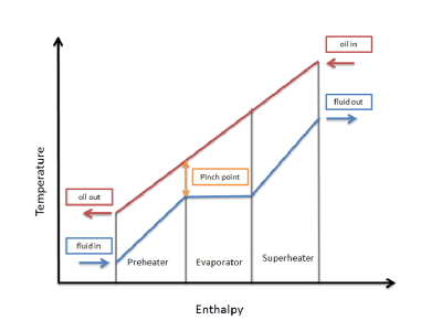
Pinch Point Analysis is a systematic process design methodology consisting of a number of concepts and techniques that ensure an optimal use of energy. The Pinch is characterized by a minimum temperature difference between hot and cold streams and designates the location where the heat recovery is the most constraint.

The fundamental computational tool is the Problem Table algorithm. This tool allows the identifications of the Pinch, as well as of targets for hot and cold utilities.

The net heat flow across Pinch is zero. Consequently, the system can be split into two stand-alone subsystems, above and below the Pinch. Above the Pinch there is need only for hot utility, while below the Pinch only cold utility is necessary. For given ΔTmin the hot and cold utility consumption identified so far becomes Minimum Energy Requirements (MER). No design can achieve MER if there is a cross-pinch heat transfer.

The partition of the original problem in subsystems may introduce redundancy in the number of heat exchangers. When the capital cost is high, it might be necessary to remove the Pinch constraint in order to reduce the number of units. The operation will be paid by supplementary energetic consumption, which has to be optimized against the reduction in capital costs.

The result is that heat recovery problem becomes an optimization of both energy and capital costs, constraint by a minimum temperature approach in designing the heat exchangers. Stream selection and data extraction are essential in Pinch Analysis for effective heat integration.

The key computational assumption in Pinch Point Analysis is constant CP on the interval where the streams are matched. If not, stream segmentation is necessary

The counter-current heat flow of the streams selected for integration may be represented by means of Composite Curves (CC). Another diagram, Grand Composite Curve (GCC) allows the visualization of the excess heat between hot and cold streams against temperature intervals. This feature helps the selection and placement of utilities, as well as the identification of the potential process/process matches.

The synthesis of a Heat Exchanger Network consists of three main activities:

  • Set a reference basis for energy integration, namely:

-Minimum Energy Requirements (MER)

-Utility selection and their placement

-Number of units and heat exchange area

-Cost of energy and hardware at MER

  • Synthesis of heat exchanger network (HEN) for minimum energy requirements and maximum heat recovery. Determine matches in subsystems and generate alternatives.
  • Network optimization. Reduce redundant elements, as small heat exchangers, or small split streams. Find the trade-off between utility consumption, heat exchange area and number of units. Consider constraints

The improvement of design can be realized by Appropriate Placement and Plus/Minus principle. Appropriate Placement defines the optimal location of individual units against the Pinch. It applies to heat engines, heat pumps, distillation columns, evaporators, furnaces, and to any other unit operation that can be represented in terms of heat sources and sinks.

The Plus/Minus principle helps to detect major flow sheet modifications that can improve significantly the energy recovery. Navigating between Appropriate Placement, Plus/Minus Principle and Targeting allows the designer to formulate near-optimum targets for the heat exchanger network, without ever sizing heat exchangers.

Pinch Point principle has been extended to operations involving mass exchange. Saving water can be treated systematically by Water Pinch methodology. Similarly, Hydrogen Pinch can efficiently handle the inventory of hydrogen in refineries. Other applications of industrial interest have been developed in the field of waste and emissions minimization. The systematic methods in handling the integration of mass-exchange operations are still in development. In this area the methods based on optimization techniques are very promising.

Plant Design

Plant design & engineering

From conducting Feasibility studies, FEED / Basic & Detail engineering during the engineering phase to providing field engineering services during construction & commissioning, a plant design & process engineering company & its services should span across the entire life cycle of projects.
Typical list of services covered under plant design & engineering include:

  • Conceptual and Techno-Economic Feasibility Studies
  • FEED & Basic Engineering
  • Pre-bid / Proposal Engineering
  • Preparation of Process Packages
  • Technology and Process Licensor Selection
  • Detailed Design & Engineering
  • Procurement & Construction Support
  • Field Engineering
  • De-bottlenecking studies and Trouble Shooting
  • Laser Scanning and 3D modeling
  • As-Built documentation
  • Decommissioning Studies

A company involved in process management & plant engineering carries out all the above activities. All the phases have to be carefully managed starting from Engineering Execution Strategy the FEED and defining the project baseline standards by establishing the codes to and procedures to be able to set Engineering Audit.

A plant design & engineering company has to maximize energy output and reduce LCOE. Since every project is different, Project specific factors such as the local irradiance, weather, soil, wind, and topography must be taken into account for the design, layout, technology selection, and system configuration.

By utilizing the plant design & engineering company’s industrial applications, facility owners will be able to more efficiently implement and execute the challenging plant design management processes.
Why Panorama as your plant design & engineering firm?

Panorama’s Plant Engineering team includes highly experienced engineers in the design and maintenance of industrial processing plants.

Our primary customer groups are those who are in the business of processing, refining, handling, manufacturing or treating petrochemicals, gases, water, waste, bulk materials, minerals, food products or manufactured products for use in other processes or for sale to others.

If you are looking to either expand your business, increase production, reduce bottlenecks, manufacture new products, improve efficiency, upgrade to new technologies, refurbish or repair – Panorama’s offering ranges from machine engineering and finite element analysis to fully integrated, multi-discipline industrial plant design.
Panorama utilises the latest 3D modelling software for each phase of project design development, from conceptual to definitive design, right through to the production of documentation for construction.

Panorama also customizes our delivery to suit the industrial plant company’s project development strategy – becoming accustomed to roles in a wide range of contractual relationships including: due diligence, design consultancy, independent inspection, EPCM, EPC, D&C, owner’s engineer, and strategic alliances.

Read more on what are the steps involved in Industrial Plant Design

Utility Systems Qualification – Backbone for the Pharmaceutical Industry

Pharmaceutical manufacturing is a highly regulated industry. Given the stress on product quality and the widespread impact of substandard production on public health and safety, utility system qualification is a critical step that companies must take towards ensuring that all their products comply with federal laws and regulations.

In pharmaceuticals, critical utilities like WFI, RODI, Compressed Air, Nitrogen, Air Handling Units (AHU) and HVAC (Heating, Ventilation and Air Conditioning) systems support the manufacturing process. As a result, these are treated as products that need to satisfy FDA regulatory requirements and pharmaceutical manufacturing standards, just like raw materials and other equipment used in the industry.

Quantitative and qualitative specifications: Utilities must pass a string of qualitative and quantitative specifications to be considered satisfactory. Different utility systems have different quality and standard criteria, designed on the basis of inputs from relevant departments and organizations as well as manufacturing and engineering provisions. When a validation program is set in place for utility systems used in pharmaceutical, critical utilities should be first on the list. It’s important to focus on the design, qualification and monitoring of each utility system used in pharmaceutical or biotech companies, so their end product fulfills all pharmaceutical quality standards.

cGMP and FDA guidelines: Utility system qualification is designed to ensure that utilities in use conform to health and safety regulations, as well as pharmaceutical manufacturing standards and cGMP guidelines. Current good manufacturing practices (cGMPs) are FDA guidelines that check the design, control and monitoring of manufacturing facilities and processes. To comply with cGMP regulations, drugs and medicinal products need to be of the right quality, strength and purity, by way of adequately controlled and monitored manufacturing operations.

Steps in utility system qualification include:

  • Implementing strong operating procedures
  • Establishing extensive quality control systems
  • Procuring a consistent quality of raw material supplies
  • Maintaining dependable testing labs

If such a broad control system is implemented in a pharmaceutical facility, it can help to control:

  • Instances of mix-ups
  • Contamination, errors
  • Defects and deviations during the manufacturing process

Such pharmaceutical products are better able to meet public health and safety laws established by the FDA.

Flexibility: Pharmaceutical cGMP guidelines are flexible enough that all manufacturers are free to decide how to apply FDA controls in ways that fit their unique requirements. They can make use of a variety of processing methods, testing procedures and scientific designs to adapt their manufacturing processes to meet the laws. Because of the flexibility of these laws, companies can use innovative approaches and sophisticated technology to implement a system of continual improvement in order to achieve a consistent quality of pharmaceutical supplies.

FDA approved regulations: All pharmaceutical manufacturing facilities need to adhere strictly to FDA-approved regulations. Failure to meet FDA regulations can result in responsive action by the authorities against the product or the responsible facility, depending upon the seriousness of non-compliance. The company may have to recall the product under orders of the FDA, to ensure it does not cause additional harm or risk to the public.

cGMP requirements can be useful in ensuring the efficacy, quality and safety of pharmaceutical products by making sure facilities are in good operating condition, with sufficiently calibrated and well-maintained equipment, trained and experienced staff and reliable and efficient processes.

While a utility system cannot affect product quality on its own, it forms an integral part of the manufacturing process. That is where Panorama Consulting and Engineering, Inc. helps the companies setting up the validation processes as per the regulatory requirements.

Design of Purified water & WFI Systems

Water is the one of the major commodities used by the pharmaceutical industry. It is widely used as a raw material, ingredient, and solvent in the processing, formulation, and manufacture of pharmaceutical products, active pharmaceutical ingredients (APIs) and intermediates, and analytical reagents. It may present as an excipient, or used for reconstitution of products, during synthesis, during production of finished product, or as a cleaning agent for rinsing vessels, equipment and primary packing materials etc.

There are many different grades of water used for pharmaceutical purposes. Several are described in USP monographs that specify uses, acceptable methods of preparation, and quality attributes. These waters can be divided into two general types: bulk waters, which are typically produced on site where they are used; and packaged waters, which are produced, packaged, and sterilized to preserve microbial quality throughout their packaged shelf life.

There are several specialized types of packaged waters, differing in their designated applications, packaging limitations, and other quality attributes.

Different grades of water quality are required depending on the different pharmaceutical uses.

Types of Water used:

Water is the most common aqueous vehicle used in pharmaceuticals. There are several types of water are used in the preparation of drug product, such as:

  1. Non potable water: It is water that is not of drinking water quality, but which may still be used for many other purposes, depending on its quality. It is generally all raw water that is untreated, such as that from lakes, rivers, ground water, springs and ground wells.
    Purposes:

    • cleaning of outer surface of the factory
    • used in garden
    • washing vehicles etc.
  2. Potable water: It is not suitable for general pharmaceutical use because of the considerable amount of dissolved solids present. These consist chiefly of the chlorides, sulphates & bicarbonates of Na, K, Ca and Mg. A 100 ml portion of water contains not more than 100 mg of residue (0.1%) after evaporation to dryness on a steam bath.
    Purposes:

    • To use as drinking water
    • Washing & extraction of crude drugs
    • Preparation of products for external use
  3. Purified water: It is used in the preparation of all medication containing water except ampoules, injections, some official external preparations such as liniments. It must meet the requirements for ionic & organic chemical purity & must be protected from microbial contamination.
    Purposes:

    • For the Production of non-parenteral preparation/formulation
    • For the Cleaning of certain equipment used in non-parenteral product preparation
    • For Cleaning of non-parenteral product-contact components
    • For All types of tests
    • For the Preparation of some bulk chemicals
    • For the preparation of media in microbiology

Water for Injection (WFI):

Water for Injection is a solvent used in the production of parenteral and other preparations where product endotoxin content must be controlled, and in other pharmaceutical applications.(WFI) is sterile, non pyrogenic, distilled water for the preparation of products for parenteral use.

It contains no added substance and meets all the requirements of the tests for purified water. It must meet the requirements of the pyrogen test. The finished water must meet all of the chemical requirements for Purified Water as well as an additional bacterial endotoxin specification.

Since endotoxins are produced by the kinds of microorganisms that are prone to inhabit water, the equipment and procedures used by the system to purify, store, and distribute Water for Injection must be designed to minimize or prevent microbial contamination as well as remove incoming endotoxins from the starting water. Water for Injection systems must be validated to reliably and consistently produce and distribute this quality of water.

Purposes:

  • For the production of parenteral products/formulation
  • For cleaning of parenteral product-contact components

Preparation technique:

  • Distillation
  • Reverse osmosis
  • Membrane process

Storage condition:

It can be stored for periods up to a month in special tanks containing ultraviolet lamps. When this freshly prepared water is stored and sterilized in hermitically sealed containers, it will remain in good condition indefinitely.

If autoclave is not available, freshly distilled water may be sterilized by boiling the water for at least 60 minutes in a flask stoppered with a plug of purified non-absorbent cotton covered with gauze, tin-foil or stout non-absorbent paper; or the neck of the flask may be covered with cellophane and tightly fastened with cord.

WFI System validation process:

How to preform WFI system validation in Pharmaceuticals and Acceptance Criteria for Water for Injection.

Process:

  1. Perform Installation Qualification. Verify piping, fittings, proper dimensions drawings, wiring, PC software, calibration, and quality of materials.
  2. Check flow rates, low volume of water supply, excessive pressure drop, resistivity drops below set point, and temperature drop or increase beyond set level.
  3. Perform general operational controls verification testing.
  4. Operate system throughout the range of operating design specifications or range of intended use.
  5. System regulators must operate within ±2 psi of design level.
  6. Operate the system per SOP for operation and maintenance of purified water system. Perform sampling over a 1 month period per the sampling procedure and schedule.
    Test samples for conformance to current USP Water for Injection monograph, microbial content and endotoxin content. Identify all morphological distinct colony forming units (CFUs) to at least the genus level
  7. Measure the flow rate and calculate the velocity of the water, or measure the velocity directly at a point between the last use point and the storage tank.
  8. Record the range of all process or equipment parameters (set points, flow rates, timing sequences, concentrations, etc.) verified during Operational and Performance Qualification testing.

Acceptance Criteria

  1. The system is installed in accordance with design specifications, manufacturer recommendations, and cGMPs. Instruments are calibrated, identified, and entered into the calibration program.
  2. General controls and alarms operate in accordance with design specification.
  3. The system operates in accordance with design specifications throughout the operating range or range of intended use.
  4. The system flow rate must be in compliance with design specifications.
  5. All samples must meet the following criteria:
    1. Chemical Testing: Test samples must meet the acceptance criteria of the chemical tests as described in USP Monograph on Water for Injection.
    2. Bacteriological Purity: All samples must contain no more than 10 cfu/100 ml; no pseudomonas or coliform are detected.
    3. Endotoxins: All samples must contain no more than 0.25 EU/ml.
    4. Physical Properties: The temperature of the hot Water for Injection must be greater than 80°C.
    5. Particulate Matter: Small Volume Injection: The Small Volume Injection meets the requirements of the test if the average number of particles it contains is not more than 10,000 per container that are equal to or greater than 10 µm in effective spherical diameter and not more than 1000 per container equal to or greater than 25 µm in effective spherical diameter.

If you require technical assistance regarding purified water & WFI systems please feel free to contact on +91-22-66735960 or use our technical support form.

Detail Engineering Piping Systems

Detailed engineering for piping systems

Detailed engineering are studies which creates a full defined scope of work for every aspect of project development. It is a multi-step process which includes conceptualization, research, feasibility analogy, establishing design requirements, preliminary design plans, detailed designing, production planning and tool design and finally moving towards actual production. Detail engineering studies are a key component for every project development across Mining, Infrastructure, energy, oil&gas sectors.

Detailed engineering companies have the best technical experts & a wide range of experience across various industries to carry out the tasks of project management at the maximum precision level.
Piping engineering is a specialised branch of detailed engineering dealing with design & layouts of piping network along with the Equipments in a process plant.

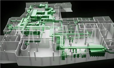
The images shown form a fully fledged blue print of a plant & are used for plant construction at site. The most important factors to be considered are:

  • Process requirements
  • Process safety
  • Operability
  • Maintenance
  • Compliance with statutory requirements & economy

2

Piping detailed engineering process:

‘Piping’ includes the utility of components such as pipe, valves and fittings. A piping designer or a piping engineering company should be thoroughly acquainted with the equipment, instrumentation and related disciplines. A team of piping detailed engineering consists of Engineers, designers and construction personnel who get together to develop and design piping and instrumentation diagrams also known as P&ID (Process & Instrumentation Diagrams).

However, the process doesn’t stop there, they also make equipment plot plans, define the piping arrangements and make fabrication drawings.
A piping engineering company performs the following processes:

  1. Preparation of plot plan, equipment layouts piping studies, piping specification
  2. Review of process package
  3. Giving inputs to civil, vessel, electrical / instrumentation groups for various purposes

A piping engineering company ideally goes through the following plan of action to initiate the project:

  • Preparation of piping layouts, isometrics, support Drawings
  • Stress analysis
  • Procurement assistance
  • Preparation of drawings for statutory approvals
  • Preview of vendor drawings
  • Coordination with various engineering groups & site

And finally ends with completion & commissioning of plant.

Detail piping engineering: What does it involve?

Detail piping engineering consists of an engineering report for the use of various types of pipes and pumps with pressure drop calculations. It also consists of:

  • Pipes and pumps specifications
  • equipment selection and size
  • instrumentation and process control
  • other piping components such as valves, fittings, piping hangers and supports

Detail piping engineering : How helpful it is to you?

Detail piping engineering focuses on 3 primary pointers:

  • how your piping systems should work;
  • what materials must be used to make the piping structure for the engineering project;
  • select the type of material to be used for certain pipes and piping components

Detailed engineering helps in drafting fabrication and construction specifications. It also helps piping consulting engineers to execute a thermal analysis, vibrating analysis and stress analysis for sound piping layout and implementation.