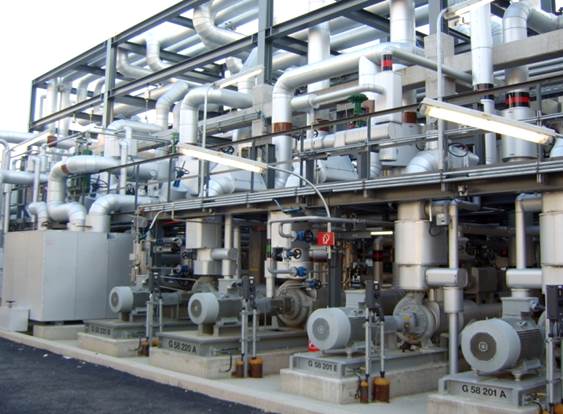
Basic engineering package – Ideal approach

A company contracted for Basic engineering design package adapts it according to the chosen scope of supply work, ranging from the delivery of key equipment to the incorporation of a complete skid-mounted unit.

Only a well qualified & experienced engineering company will be able to successfully execute detail engineering, equipment procurement, preparation of the final plant operating manuals, plant construction etc which ensures a complete delivery cycle of a basic engineering package.

For the delivery of a skid-mounted unit, assembling should take place in fabrication workshops, the documentation should focus more on ways to utilize the unit.
BEP Meetings

The engineering company’s constant contact with the owners of industrial plants is a must during the execution of the basic engineering to ensure:

  • All local conditions and regulations are considered
  • The necessary agreement and understanding on of industrial units chosen technologies is considered.
  • Exchange of information about the actual status during basic engineering performance

Typical meetings:

  • Kick-start meeting to agree on the basic data
  • Intermediate meeting to present & visualize first results and agree on challenges encountered
  • Meeting to present the basic engineering documentation
  • A detail engineering review meeting

Both during and after the execution of a basic engineering project, the engineering company should provide several additional services that are essential to design, construct, install and run the unit.
For example:

  • Supporting documentation for authorities
  • Participating at HAZOP and other safety related meetings
  • Support during commissioning
  • Support during start-up
  • Participation in performance test runs
  • Support for later plant modifications involving issues like de-bottlenecking, capacity increases etc.

Basic engineering package design – Checklist

  • Design Basis
  • Process Description
  • Equipment List
  • Process Flow Diagrams and Heat & Material Balances
  • Piping and Instrumentation Diagrams
  • Process Equipment Data Sheet
  • Instrument List
  • Piping
  • Control Philosophy
  • Effluent stream list

List of vapor emission sources

  • Composition and flow rate of process off gas and evaluation of whether this material can be sent to the hot oil heater or must be sent to a thermal oxidizer.
  • Hot Oil Heater and Steam Generation Boiler characteristics, evaluation of flue gas treating requirements and definition of effluent flue gas treating system requirements
  • Liquid Effluent Streams
  • Solid Waste quantities and type
  • By-product quantities and characteristics

Quality Assurance and Laboratory Information

Utilities Consumption

Panorama’s highly experienced engineers have extensive chemical process engineering expertise in oil and gas, refining, gasification, petrochemical, pharmaceutical and specialty chemicals.

Pinch analysis & Process integration services

In a highly competitive global economy, maximizing results by eliminating costly inefficiencies is critical.

Chemical & Process Industries in India consume lots of Energy; the primary usage being Heating, Cooling, and Electrical Power.

Traditional attempts to reduce energy only focused on individual piece of equipments & units. Process Integration involves a streamlined & systematic “Total site -as a whole” approach towards use of Heating/Cooling Requirements, electrical power and water. Process Integration ensures maximum advantages by providing alternative designs and structured road maps for long term energy savings.

Though Process Integration covers a wide area, pinch analysis companies & process integration services companies focus mainly in Facilities where Distillation consumes major energy, and where lots of waste energy is available.

Reactions like Nitration, Oxidations and Hydrogenations evolve a lot of heat due to exothermic nature. Typically these reactions, distillation processes or other downstream operations consume considerable amount of heat.

Thus, the concept of having continuous processing of these reactions to utilize the heat evolved in downstream operation integrates the process that can result in significant savings and safe operations.

See how Panorama can help you migrate from batch reactions to continuous ones by piloting the whole process till commercial levels.

Up till now, Process Integration is in use at bigger plants, Panorama’s idea is to make it work in smaller plants as well.

Process Integration Methodology:

  • Generating heat & material balances by optimizing simulation services
  • Performing energy analysis to identify alternatives
  • Make modifications in processing conditions
  • Redesign equipments in the light of above changes.
  • Analyze cost data and finalize proposal.

Waste Heat Recovery Units (WHRU)

The exhaust gas of various processes or even from the exhaust stream of processes & conditioning units generates waste heat which can be used to generate useful heat and reduce fuel consumption.

There are many different commercial recovery units for the transferring of energy from hot medium to cold one:

  • Recuperators
  • Regenerators
  • Heat pipe exchanger
  • Economizers
  • Heat pumps etc

Combined Heat and Power (CHP)

Waste heat of different degrees can be found in final products of certain process or as a by-product in industries like steelmaking plants. Units or devices that could recover the waste heat and transform it into electricity are called CHPs. Such units, for example, use an Organic Rankin Cycle (ORC) with an organic fluid as the working fluid. The fluid has a lower boiling point than water to allow it to boil at low temperature, to for a superheated gas that could drive the blade of a turbine and thus a generator.

Panorama’s offerings

  • Process Integration solutions
  • Energy analysis solutions
  • Batch to Continuous Processing Migration Solutions
  • Waste Heat Recovery -Simple Solutions involving heat recoveries only.
  • Waste Heat Recovery- Comprehensive solutions including CHP (Combined Heat Power)

Panorama maximizes energy efficiency in both initial design and ongoing operations through best practices pinch analysis. Thermal Pinch Analysis & Process Integration is a systematic methodology for determining optimal energy efficiency. In most cases we find millions of dollars of annual operational savings (in facilities more than 15 years old). For Greenfield development we enable process engineers to properly integrate pinch tools into the conceptual process design phase, on which the foundation of the entire lifecycle is built.

For existing facilities, Panorama provides the most effective action plan by understanding complete energy balance for maximum efficiency, identifying suboptimal energy exchange between process streams, and analyzing the most cost effective balance between energy savings and capital expenditure to achieve optimal efficiency.

On short notice, our experts can pull together engineering scopes and feasibility studies to produce ready-to-use initial design work.

Our onsite dedicated teams are available to directly interact with the process specialists, should onsite be preferred to remotely analyzing. Regardless of geography, we use the highest thermodynamic principles to systematically analyze chemical processes and surrounding utility systems.

Panorama’s pinch analysis results in financial savings through better process heat integration.

Fire pump design – A complete guide

When you embark on a fire pump design in India, one of the most important things to consider is your water supply. If you will use your city’s water supply as the main source for your pump, you’ll need to ensure that an accurate and thorough test of the city water is done. Some rules to follow include:

  • Make sure that your water test is no older than a year.
  • Make sure that the water test is done close to the tap as possible.
  • Ensure your test is done during the highest time of water usage in your area.

In cold climate areas like Jammu and Kashmir, Ultarakhand, Himachal Pradesh and Sikkim or anywhere around the Himalayan area, testing during summer will be most ideal as many residents and commercial properties will be watering their crops and using water to cool down. In addition, in high density areas, peak times for water usage in the morning are between 6 am and 9am, and this may be the most ideal time for testing.

Another point to consider with regard to your water test will be: Does the city supply sufficient water to meet 150% of your fire pump design? This ensures that the city supply will carry enough volume to meet system demand. If this however isn’t the case, request another test this time plotting a water supply curve or using hydrants.

If your water supply is from a private source such as a ground storage tank or lake, keep in mind that some jurisdictions don’t allow using suction lift with fire pumps. This then means, if your water supply is below the suction inlet to your fire pump, you’ll need to use a lone vertical turbine pump in preference to the different kinds of pumps available.

Your final job parameter to size your fire pump will be required water flow for the systems that the pump will serve (standpipes, sprinklers and or others). If you use standpipe systems, the flow will be related to size and type of structure the pump will be protecting. In whichever case, the system demand will dictate the flow and pressure required.

Avoid Problems

In your effort to avoid any troubles that may arise during your fire pump design and installation process, make sure you do some thorough research and consult with local authorities in your jurisdiction and insurance representatives before you embark.

Certain jurisdictions have different requirements for the design and installation of fire pumps. Regulations in Punjab Province may require suction control valves for all fire pumps to prevent falling below 20 psi within the main, and those in Delhi may be different. Insurance companies will also have their different requirements for installing fire pumps. Do your research, get the necessary paperwork to ensure a smooth process.

Pharma Validation Services

All Pharma validation services companies provide a comprehensive validation service at every stage of the project life cycle. These companies assist with all aspects of validation relating to equipment, facilities, GMP utilities and computer systems. Pharma validation services ensures support to clients in developing, implementing and achieving a validation strategy and programme that is designed to meet the customers’ timescales and budget whilst fully satisfying the cGMP requirements and the regulatory obligations of the licensing bodies.

It begins from the design stages of a project i.e. during User Requirement Specification (URS) development, Design Reviews right through Vendor Factory Acceptance Testing (FAT) to site Commissioning, Installation Verification and Qualification (IQ), Operational Testing and Qualification (OQ) and Performance Qualification (PQ).

Pharma validation services typically include:

  • Validation Master Plans / Validation Plans.
  • Design Qualification.
  • Design Reviews Support.
  • Computer Systems Report.
  • Installation Qualification (IQ) Protocols.
  • Site Validation Execution.
  • Operation Qualification (OQ) Protocols.
  • Final Validation Summery Reports.
  • Performance Qualification (PQ) Protocols.
  • Cleaning / Sanitation Validation Protocols.

All projects should be delivered by the engineering company with a precise level of Project Management, Scheduling and Cost Control Metrics to monitor progression.

The engineering company providing Pharma validation services has to carefully plan the entire process cycle of the project. The guiding document on qualification & validation of the object has to be the Validation master plan. Along with the technical expertise, the pharma validation services company cannot ignore the importance of including several specialists i.e. technologists, engineers, metrologists etc.

Qualification & Validation Areas of Pharma companies:
The qualification phase pertains to actions given how a specific equipment gives the expected results & works properly.

Qualification stages:

  • Design qualification
  • Installation qualification
  • Operation qualification
  • Performance qualification

Validation stages:

Validation phase relates to actions that in accordance with the principles of good manufacturing practice prove that a specific method, approach, process, equipment etc gives the expected results.

Validation services:

  • Validation of sterilization process
  • Media fills
  • Process validation
  • Cleaning validation
  • Validation of the cold chain
  • Validation of the monitoring, the automated control systems

List of activities:

Typical pharma validation services companies prepare the following reports:

Production premises:

  • Clean rooms
  • Isolators & other barrier systems
  • HVAC systems

Sterilization:

  • Steam sterilization
  • Dry heat sterilization
  • Ethylene oxide sterilization
  • Formaldehyde sterilization
  • Depyrogenation
  • SIP systems

Washing & Cleaning processes:

  • CIP systems
  • Primary packaging & Auxiliary materials washing
  • Cleaning validation

Pure media

  • Water for injection
  • Highly purified water
  • Clean steam
  • Compressed air, nitrogen & other gases

Other production processes / Production of equipments:

  • Preparation of solutions, ointment bases
  • Dry powder filling
  • Lyophilization
  • Decontamination of external surfaces
  • Optical control
  • Granulation
  • Homogenization
  • Tableting, coating, capsule filling
  • Blister packaging
  • Cartoner, group packaging
  • Labelling
  • Cross contamination
  • Process validation

Sampling zones / Warehouses:

  • Clean rooms
  • HVAC
  • Direct air flow zones
  • Special storage conditions chamber
  • Validation of cold chain processes

Monitored, automated control systems:

  • Production premises
  • Pure media
  • Production equipment
  • Production processes
  • Production storage & warehousing

Laboratories, hospitals, clinics, pharmacies etc.

  • Clean rooms
  • HVAC systems
  • Laminar boxes, isolators, biological safety cabinets
  • Thermostats, incubators, refrigerators, freezers
  • Stabilization boxes
  • Sterilization & depryogenation processes
  • Washing, cleaning & Decontamination processes

It’s a simple question, not always the easiest to answer. Which could be the best pharma validation services company? How to evaluate? Panorama’s pharmaceutical compliance and validation services combined with pharmaceutical consultancy services are all aimed at making this an easier question to answer.

Improved Energy Consumption Via Heat Integration & Pinch Analysis

A respected tool for achieving energy efficiency is process heat integration with pinch analysis. This article presents an overview on pinch analysis and its mode of employment in operation and process design to achieve energy efficiency gains in real-world. The Heat integration comprises of several techniques that assist engineers to properly evaluate entire sites and processes instead of focusing on individual operations.

This includes knowledge-based systems, hierarchical design methods, Pinch analysis, numerical and graphical techniques. Pinch methods dominate in the area of energy efficiency. The terms heat integration (PI) and pinch analysis are frequently used interchangeably.

Pinch analysis which is also known as process integration, energy integration, heat integration or pinch technology is employed in achieving minimal energy consumption by optimizing energy supply methods, process operation conditions and heat recovery systems. It is a methodology for minimizing the consumption of energy through chemical processes by targeting feasible energy targets thermodynamically.

As a systematic technique for analyzing the flow of heat through an industrial process, pinch analysis’ process data is represented as a set of streams or energy flows. Naturally, heat is required to flow from hot to cold objects in the Second Law of Thermodynamics. This is a major concept that represents the overall heat demand and heat release of a process as a function of temperature.

For the identifications of the Pinch and targets for cold and hot utilities, the Problem Table algorithm is the tool to use. It is a fundamental computational tool. The location where the heat recovery is the most constraint is designated by the Pinch which is characterized by ΔTmin (a minimum temperature difference between hot and cold streams).

As a result, the system can be divided into two separate subsystems that are located above and below the Pinch respectively. Hot utility is only required above the Pinch while cold utility is required below the Pinch. So far, the identified hot and cold utility consumption turns out to be Energy Requirements (MER). Once a heat transfer (cross-pinch) is present, no design can achieve MER.

Redundancy many be introduced by the separation of the original problem in the number of heat exchangers. In order to reduce the number of units, the removal of the Pinch constraint may be necessary especially when the capital cost is high. An optimized cost of operation against the reduction in capital costs will be cleared by extra energetic consumption.

As a result, heat recovery problem will become an optimization of both capital and energy costs which is restricted by a minimum approach in temperature when designing the heat exchangers. For effective heat integration, there is need for data extraction and stream selection in Pinch Analysis. Constant CP is the major computational assumption in Pinch Analysis.